Performance Check—2465B/2467B Service
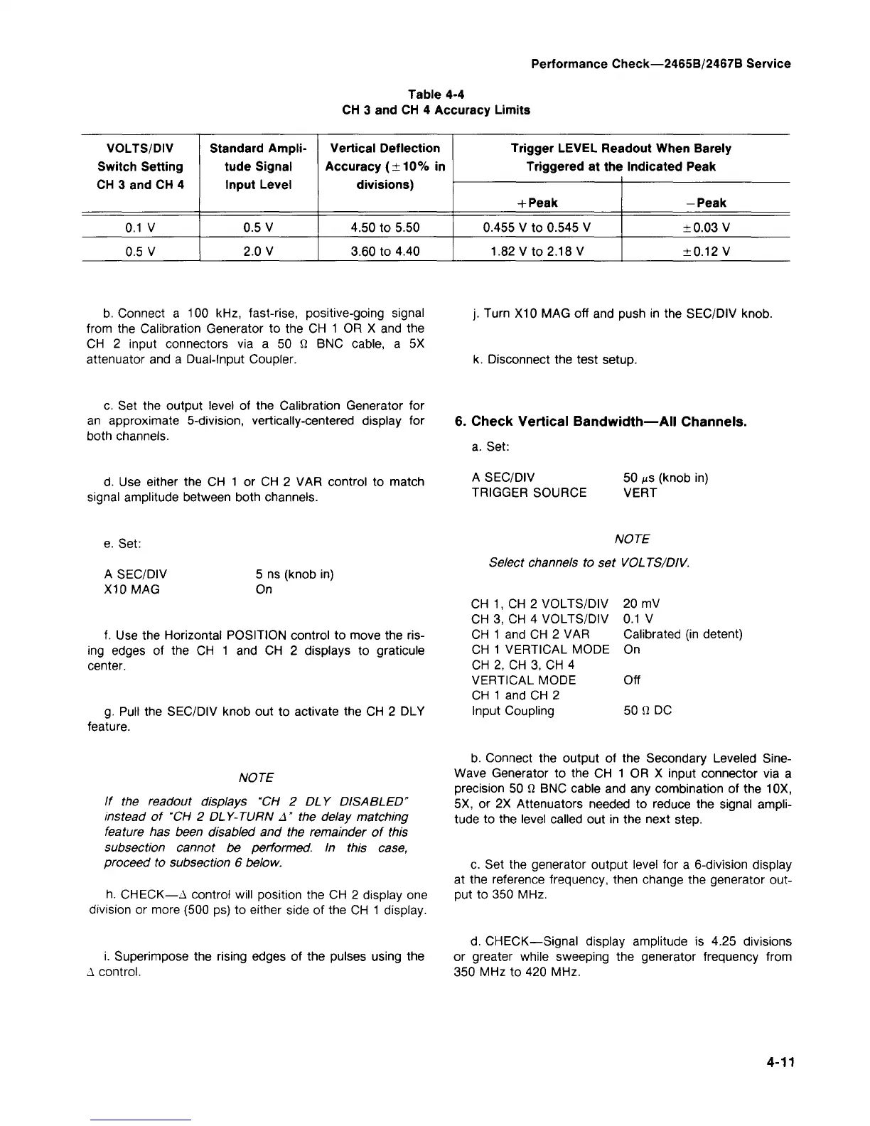
Table 4-4
CH 3 and CH 4 Accuracy Limits
VOLTS/DIV
Switch Setting
CH 3 and CH 4
0.1 V
0.5 V
Standard Ampli-
tude Signal
Input Level
0.5 V
2.0 V
Vertical Deflection
Accuracy (±10% in
divisions)
4.50 to 5.50
3.60 to 4.40
Trigger LEVEL Readout When Barely
Triggered at the Indicated Peak
+
Peak
0.455 V to 0.545 V
1.82 V to 2.18 V
-Peak
±0.03 V
±0.12 V
b. Connect a 100 kHz, fast-rise, positive-going signal
from the Calibration Generator to the CH 1 OR X and the
CH 2 input connectors via a 50 fi BNC cable, a 5X
attenuator and a Dual-Input Coupler.
Turn X10 MAG off and push in the SEC/DIV knob.
k. Disconnect the test setup.
c. Set the output level of the Calibration Generator for
an approximate 5-division, vertically-centered display for
both channels.
6. Check Vertical Bandwidth—All Channels.
a. Set:
d.
Use either the CH 1 or CH 2 VAR control to match
signal amplitude between both channels.
A SEC/DIV
TRIGGER SOURCE
50 us (knob in)
VERT
e. Set:
A SEC/DIV
X10 MAG
5 ns (knob in)
On
f. Use the Horizontal POSITION control to move the
ris-
ing edges of the CH 1 and CH 2 displays to graticule
center.
g.
Pull the SEC/DIV knob out to activate the CH 2 DLY
feature.
NOTE
Select channels to set VOLTS/DIV.
CH 1, CH 2 VOLTS/DIV
CH 3, CH 4 VOLTS/DIV
CH 1 and CH 2 VAR
CH 1 VERTICAL MODE
CH 2, CH 3, CH 4
VERTICAL MODE
CH 1 and CH 2
Input Coupling
20 mV
0.1 V
Calibrated (in detent)
On
Off
50 fi DC
NOTE
If the readout displays "CH 2 DLY DISABLED"
instead of "CH 2 DLY-TURN A" the delay matching
feature has been disabled and the remainder of this
subsection cannot be performed. In this case,
proceed to subsection 6 below.
h. CHECK—A control will position the CH 2 display one
division or more (500 ps) to either side of the CH 1 display.
i. Superimpose the rising edges of the pulses using the
A control.
b. Connect the output of the Secondary Leveled Sine-
Wave Generator to the CH 1 OR X input connector via a
precision 50 fi BNC cable and any combination of the 10X,
5X, or 2X Attenuators needed to reduce the signal ampli-
tude to the level called out in the next step.
c. Set the generator output level for a 6-division display
at the reference frequency, then change the generator out-
put to 350 MHz.
d.
CHECK—Signal display amplitude is 4.25 divisions
or greater while sweeping the generator frequency from
350 MHz to 420 MHz.
4-11
 Loading...


