Troubleshooting
CAUTION: Before performing this or any other procedure in this manual, read the General Safety Summary and Service Safety
Summary found at the beginning of this manual.
T
o prevent possible injury to service personnel or damage to electrical components, please read information on Preventing ESD.
(See Preventing ESD on page 15.)
This section contains information and procedures designed to help you isolate faults to a module.
This section requires that service personnel have the appropriate skills to work on this instrument, including PC troubleshooting and
Microsoft Windows operating system skills. Details of PC and Windows operation and service are not in this manual.
For assistance, contact your local Tektronix Service Center.
Service level
This subsection contains information and procedures to help you determine if a faulty power supply is the problem with your instrument. If
replacing the power supply does not fix the fault, you will need to return the instrument to a Tektronix Service Center for repair, as no other
internal electronic assemblies or modules are user-replaceable.
Check for common problems
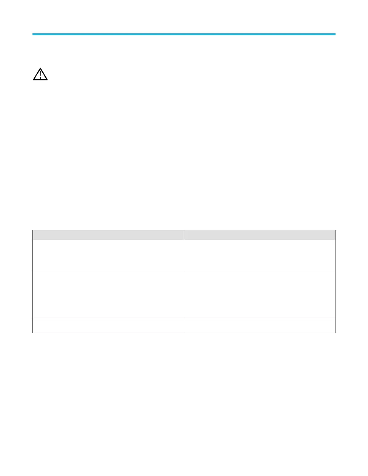
Use the following table to help isolate possible failures. The table lists problems and possible causes. The list is not exhaustive, but it may
help you eliminate a problem that is quick to fix, such as a loose power cord. For more detailed troubleshooting, see the Troubleshooting
flow chart on page 30.
Table 4: Failure symptoms and possible causes
Symptom Possible cause(s)
Instrument will not power on
• Power cord not plugged in
•
Faulty power supply
• Defective micro-controller assembly
Instrument powers on, but one or more fans will not operate
• Faulty fan power cable
• Fan power cable not connected to circuit board
• Defective fan
• Faulty power supply
• One or more defective point of load regulators
Flat-panel display blank or has streaks in display
• Faulty LCD screen or video circuitry.
Equipment required
•
Digital voltmeter to check power supply voltages.
• 0.1 inch spacing 2-pin jumper.
• An antistatic work environment.
Troubleshooting flow chart
Follow the troubleshooting flow chart to determine the action for a fault condition.
Maintenance
4 Series MSO (MSO44, MSO46) Service 30

 Loading...