Power-On and Power-Off Procedure
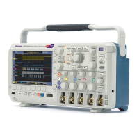
5. Push Autoset
. The screen should now display a square wave, approximately
5Vat1kHz.
NOTE. For best performance, it is recommended that you set the Vertical scale to
1V.
If the signal appears but is misshapen, perform the procedures for
compens
ating the probe. (See page 20.)
If no signal appears, rerun the procedure. If this does not remedy the situation,
have th
e oscilloscope serviced by qualified service personnel.
Compensating a Passive Voltage Probe
Whene
ver you attach a passive voltage probe for the first time to any input channel,
compensate the probe to match it to the corresponding oscilloscope input channel.
To pr
operly compensate your pas sive probe:
1. Follow the steps for the functional check. (See page 19.)
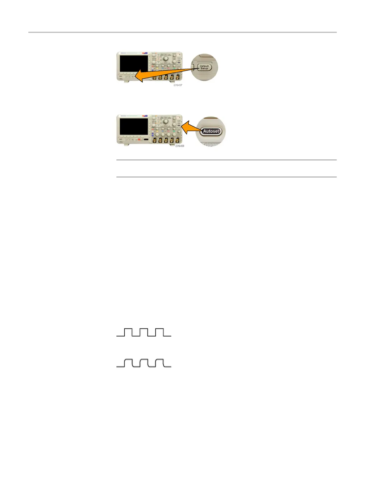
2. Check the shape of the displayed waveform to determine if your probe is
properly compensated.
Figure 3: Properly compensated
Figure 4: Under compensated
20 MSO2000B and DPO2000B Installation and Safety Instructions
 Loading...