Home
Tektronix
Test Equipment
MDO3014
Tektronix MDO3014 User Manual
5
of 1
of 1 rating
243 pages
Give review
Manual
Specs
To Next Page
To Next Page
To Previous Page
To Previous Page
Loading...
Get
Acquainted
w
ith
the
Instrument
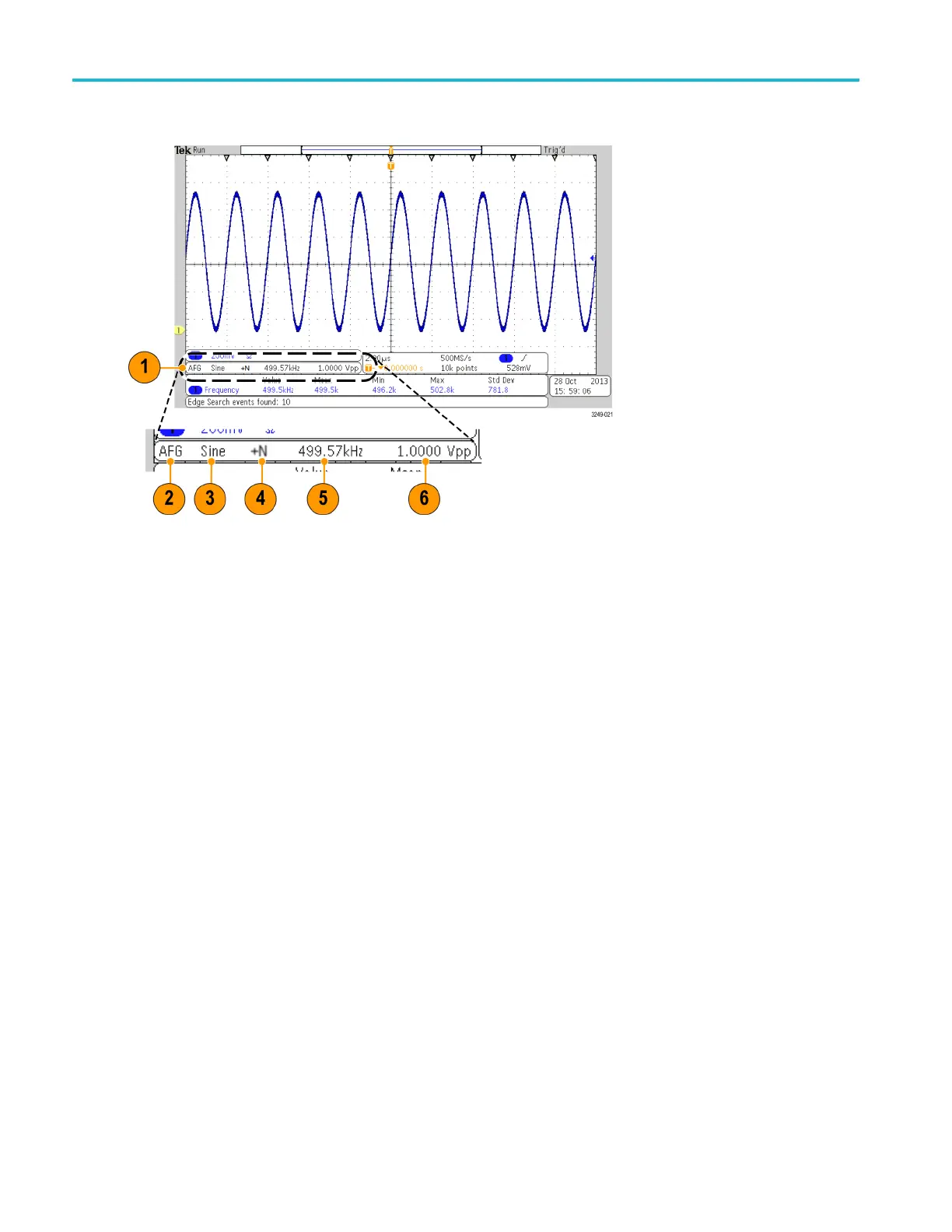
Identifying
Items
in
the
Arbitrary
Function
Generator
Display
1.
If
visible,
the
output
is
on
2.
AFG
label
3.
W
aveform
type,
e.g.
“Sine”
4.
Additive
Noise
icon
5.
Frequency
6.
Amplitude
(See
page
185,
Use
the
Arbitrary
Function
Generator
.)
50
MDO3000
Series
Oscilloscopes
User
Manual
71
73
Table of Contents
Table of Contents
7
Important Safety Information
11
General Safety Summary
11
Service Safety Summary
14
Terms in this Manual
15
Symbols and Terms on the Product
15
Compliance Information
16
EMC Compliance
16
Safety Compliance
17
Environmental Considerations
20
Preface
21
Key Features
22
Conventions Used in this Manual
22
Installation
23
Before Installation
23
Operating Considerations
27
Connecting Probes
29
Securing the Oscilloscope
30
Powering on the Oscilloscope
31
Powering off the Oscilloscope
32
Functional Check
32
Compensating a TPP0250, TPP0500B or TPP1000 Passive Voltage Probe
33
Compensating a Non-TPP0250, Non-TPP0500B or Non-TPP1000 Passive Voltage Probe
35
Application Module Free Trial
36
Installing an Application Module
36
Upgrading Bandwidth
37
Changing the Language of the User Interface or Keyboard
40
Changing the Date and Time
42
Signal Path Compensation
43
Upgrading Firmware
45
Connecting Your Oscilloscope to a Computer
48
Connecting a USB Keyboard to Your Oscilloscope
57
Get Acquainted with the Instrument
58
Front-Panel Menus, Controls, and Connectors
58
Front Panel Menus and Controls
59
Front Panel Connectors
74
Side-Panel Connector
74
Rear-Panel Connectors
75
Acquire the Signal
76
Setting up Analog Channels
76
Using the Default Setup
79
Using Autoset
80
Acquisition Concepts
81
Using Fastacq
82
How the Analog Acquisition Modes Work
84
Changing the Acquisition Mode, Record Length, and Delay Time
84
Using Roll Mode
86
Act on Event
87
Setting up a Serial or Parallel Bus
89
Setting up Digital Channels
103
When and Why to Turn on Magnivu
105
Using Magnivu
105
Setting up the RF Inputs
106
Trigger Setup
111
Triggering Concepts
111
Trigger Holdoff
112
Trigger Coupling
112
Slope and Level
113
Choosing a Trigger Type
114
Selecting Triggers
115
Triggering on Buses
117
Checking Trigger Settings
122
Using Sequence Trigger (a (Main) and B (Delayed))
122
Starting and Stopping an Acquisition
124
Display Waveform or Trace Data
125
Adding and Removing a Waveform
125
Setting the Display Style and Persistence
125
Setting the Graticule Style
127
Setting Waveform Intensity
129
Scaling and Positioning a Waveform
130
Setting Input Parameters
131
Positioning and Labeling Bus Signals
135
Positioning, Scaling, and Grouping Digital Channels
135
Viewing Digital Channels
137
Annotating the Screen
137
Viewing the Trigger Frequency
138
Displaying the Frequency Domain Menu
139
Analyze Waveform or Trace Data
143
Using Markers in the Frequency Domain
143
Taking Automatic Measurements in the Time Domain
146
Selecting Automatic Measurements in the Time Domain
147
Customizing an Automatic Measurement in the Time Domain
150
Taking Automatic Measurements in the Frequency Domain
154
Taking Digital Voltmeter Measurements
155
Taking Manual Measurements with Cursors
156
Setting up a Histogram
160
Using Math Waveforms
163
Using FFT
164
Using Advanced Math
167
Using Spectrum Math
168
Using Reference Waveforms and Traces
169
Using Wave Inspector to Manage Long Record Length Waveforms
171
Auto-Magnify
176
Limit and Mask Testing
177
Making Video Tests
181
Making Automated Power Measurements
182
Save and Recall Information
184
Saving a Screen Image
186
Saving and Recalling Waveform and Trace Data
187
Saving and Recalling Setups
190
Saving with One Button Push
192
Managing Drives, Directories, and Files
193
Mounting a Network Drive
193
Printing a Hard Copy
194
Using Oscilloscope Security Features
202
Use the Arbitrary Function Generator
207
Use the Application Modules
213
Appendix A: Warranted Specifications
215
Appendix B: TPP0250, TPP0500B and TPP1000: 250 Mhz, 500 Mhz and 1 Ghz 10X Passive Probes Information
220
Operating Information
220
Connecting the Probe to the Oscilloscope
220
Compensating the Probe with MDO3000 Series Oscilloscopes
220
Standard Accessories
220
Optional Accessories
222
Replacing the Probe Tip
223
Specifications
223
Performance Graphs
223
Safety Summary
225
Appendix C: P6316 General-Purpose Logic Probe Information
227
Product Description
227
Connecting the Probe to the Oscilloscope
227
Connecting the Probe to Your Circuit
228
Functional Check
228
Typical Application
229
Accessories
230
Specifications
231
Safety Summary
231
Safety Terms and Symbols in this Manual
232
Appendix D: Openssl License
233
Index
237
Other manuals for Tektronix MDO3014
Installation And Safety Instructions
140 pages
5
Based on 1 rating
Ask a question
Give review
Questions and Answers:
Need help?
Do you have a question about the Tektronix MDO3014 and is the answer not in the manual?
Ask a question
Tektronix MDO3014 Specifications
General
Brand
Tektronix
Model
MDO3014
Category
Test Equipment
Language
English
Related product manuals
Tektronix MDO3034
243 pages
Tektronix MDO3024
243 pages
Tektronix MDO3054
243 pages
Tektronix MDO3000 Series
26 pages
Tektronix MDO34
282 pages
Tektronix MDO32
282 pages
Tektronix MDO3104
243 pages
Tektronix MDO4104
121 pages
Tektronix MDO4104C
21 pages
Tektronix MDO4104-6
222 pages
Tektronix MDO4104-3
222 pages
Tektronix MDO4054-3
222 pages
 Loading...


