Theory of operation
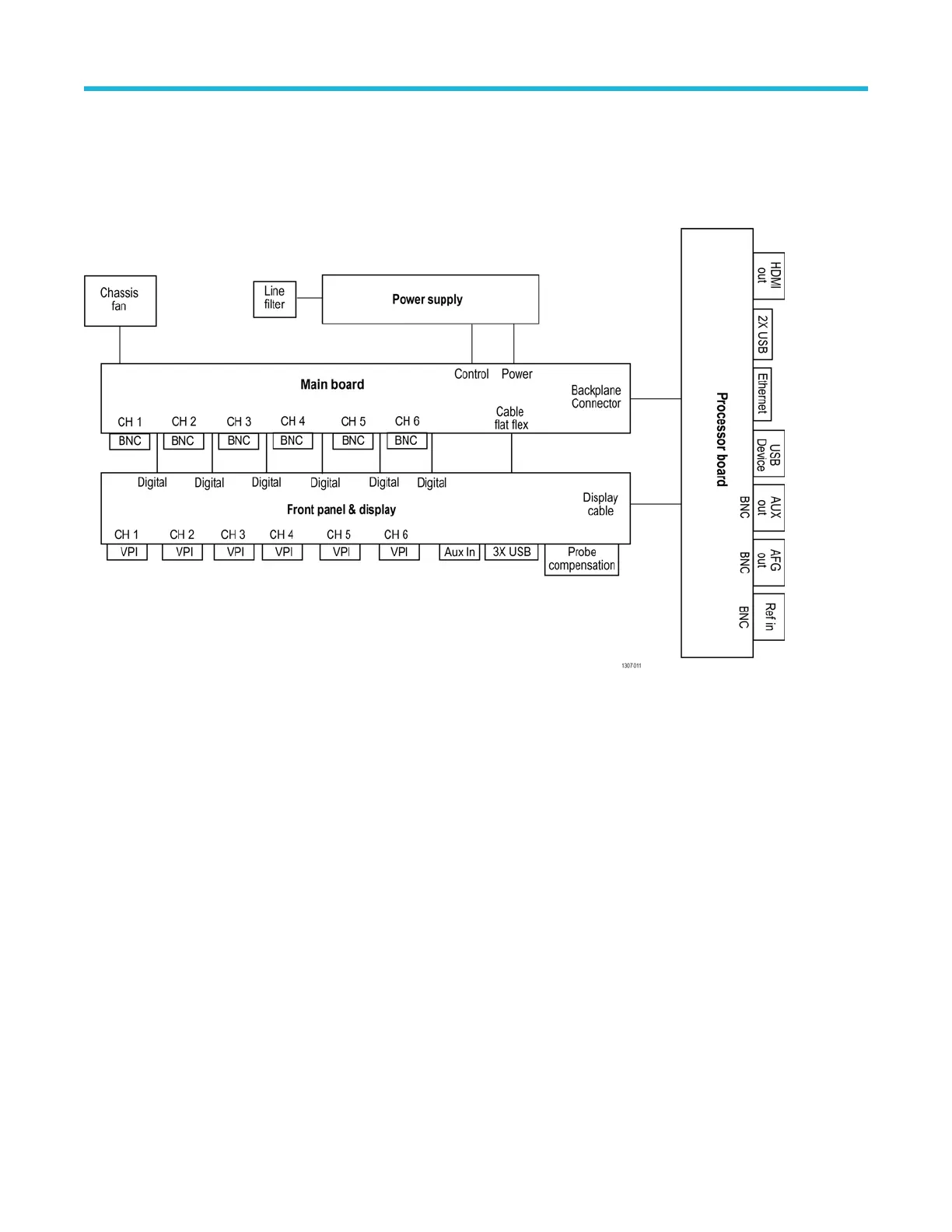
This chapter describes the electrical operation of the oscilloscope to the module level. The block diagram shows the oscilloscope module
interconnections.
Figure 1: 4 Series MSO block diagram
Power supply
The Power Supply board converts AC line voltage to +12 V to power for all internal circuits.
Processor board
The processor board contains the following functions:
Processor system The processor system contains a microprocessor that controls the entire instrument. The processor system
also contains the flash memory for the operating system, system RAM, and interfaces to I/O ports and the
acquisition system.
Rear panel I/O ports The processor board contains USB ports, an Ethernet port (LAN), a HDMI Video port, the USB-TMC port,
an AUX OUT BNC connector
, an EXT REF IN BNC connector, and the AFG Out generator BNC connector.
Other functions The processor board also houses the AFG generator, USB-TMC controller and USB host hub.
Main board
The Main board contain the following functions:
Acquisition system The Acquisition system begins with the analog signal path and ends with a digitized signal in memory. The
signal enters a channel input, and then passes through an attenuator and preamplifier
. The analog signal
Theory of operation
4 Series MSO (MSO44, MSO46) Service 12

 Loading...


