Pinpoint trigge
rs
10. In this example, a DDR3 DQS signal is
on Ch 1 and the DQ signal is on Ch 2.
The i nstrumen
t is in Run Mode with
Display Mode set to Infinite Persistence.
The instrument trigger setup was as
follows:
A-Event Window trigger on Ch 1
to detect the DD R 3 DQS Write
condition.
B-Event Edge trigger on Either slope
on Ch 1 to trigger on the DQS (clock)
edges.
A->B Sequence s et to Trig on the
nth Event.
B Scan Enab
led with Start Event
= 1, End Event = 8, and Mode =
Sequential.
The data ey
es are formed by the DQ
signal on Ch 2.
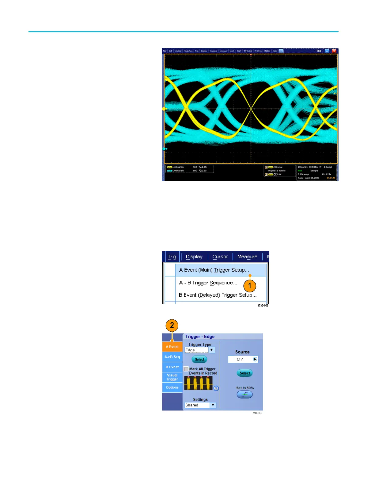
Triggering on a parallel bus
Locate problems by triggering on a parallel bus. MSO instruments can use digital channels as components of a parallel bus.
1. Set up a parallel bus. (See page 53,
Setting up a bus.) Se lect Trig > A Event
(Main) Trigger Setup....
2. Select the A Event tab.
80 MSO/DPO70000DX, MSO/DPO70000C, DPO7000C, and MSO/DPO 5000B Series U ser M anual
 Loading...


