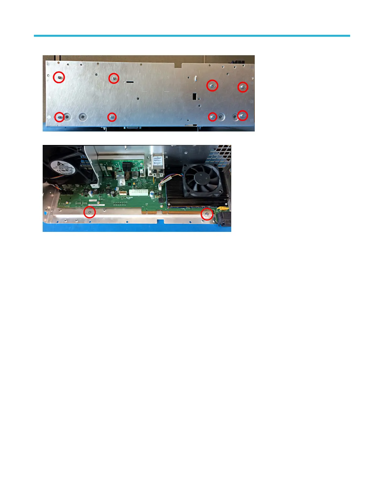
4. Use a T
-10 Torx screwdriver to remove the eight screws on the bottom of the chassis.
5. Use a T
-8 Torx screwdriver to remove the two screws on the top front edge of the of the carrier interface chassis.
6. Lift the front edge of the carrier interface assembly tray to clear the two shallow screw posts from the last step, then pull away from the
chassis. There will be a slight resistance due to the springs on the rear of the chassis for the I/O connectors.
7. To reinstall, reverse the steps. Tighten all T-10 Torx screws to 0.65 N·m when reinstalling. Tighten all T-8 Torx screws to 0.45 N·m
when reinstalling. Tighten the jack screws to 0.45 N·m when reinstalling. Reconnect the main fan cable and the power supply cables.
Remove the AFG riser assembly
Use this procedure to remove and replace the AFG riser assembly from the carrier interface assembly. Only use this procedure as part of
the sanitize process before sending the instrument for repairs at a Tektronix Service Center.
Before you begin
• To prevent electrostatic damage to components whenever you work on the instrument, wear properly-grounded electrostatic prevention
wrist and foot straps, and work in a tested antistatic environment on an antistatic mat.
• Remove carrier interface assembly on page 24. The carrier interface assembly must be removed from the rear chassis before
removing the AFG riser assembly. There is not enough clearance for the BNC and video connectors to remove the assembly while it is
installed in the chassis.
Procedure
1. Use a T-10 Torx screwdriver to remove the one screw on the AFG riser assembly bracket.
Maintenance
5 Series MSO Service Manual MSO54, MSO56, MSO58 26

 Loading...


