Theory of operation
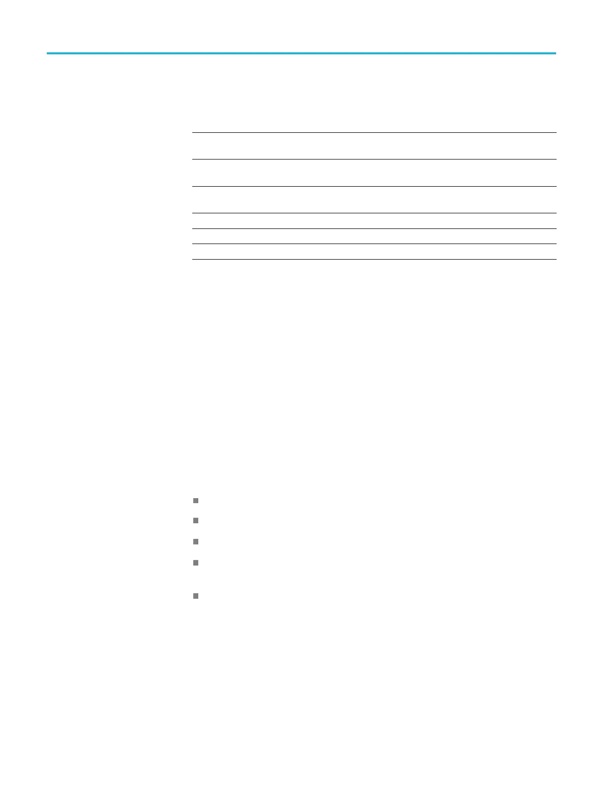
Table 1-1: Rear panel connectors (cont.)
Name
Input or
Output
Connector
type Description
Line In (blue)
Input 3.5 mm
mono
Audio line input (disabled)
MIC In (pink)
Input 3.5 mm
mono
Audio input signal (microphone)
Headphone
Output
3.5 mm
stereo
External headphone connection
+28 VDC Output BNC
Noise source drive power
GPIB Input/Output
IEEE-488
General Purpose Interface Bus
Zero-span
Output BNC
Zero-span output connector
Power supply
The Power conversion board provides instrument power. The Power conversion
board consists of several switching supplies that translate and balance the power
taken from the power supply module.
Power is distributed from the Power conversion board to both the RF Deck and
the Digital interface board.
The ON/STBY switch, located on the front panel, controls all of the power to the
instrument except for the part of the circuitry in the standby power supply.
Fans
Several fans provide cooling to the instrument:
Three fans are located in the RF Deck and are controlled by the RF Interface.
Two fans provide cooling for the Digital Deck of the instrument.
The power supply module has an internal fan.
The COM Express PC board has a fan that is controlled by the COM Express
PC board.
The optional DPSA board contains a fan.
1–4 RSA5100B Series Service Manual
 Loading...


