Operating requirements
Environment requirements
Characteristic Description
Operating
temperature
0°Cto+50°C,with5°C/minutemaximum
gradient, noncondensing (NC), up to
3000 meter altitude
Operating
humidity
5% to 95% relative humidity (% RH) up to
+30 °C
5% to 60% RH above +30 °C up to +50 °C, NC
Operating
altitude
Up to 3000 meters (9842 feet)
Power requirements
Characteristic Description
Power source
voltage
100 V
AC
–240V
AC
±10% RMS, single phase
Power source
frequency
50/60 Hz over entire source voltage range
400 Hz (360 Hz to 440 Hz) for 115 V
AC
(100 V
AC
–132V
AC
) RMS source voltage range
Power
consumption
All models: 80 W maximum
Installation
Power on the unit
1. Power the unit on by connecting the supplied power cord
to the rear-panel power connector.
2. Push the power button on the top of the oscilloscope to
turn the oscilloscope on.
To power the oscilloscope off, push the power button on the
top of the oscilloscope again. To remove power completely,
disconnect the power cord from the rear-panel of the
oscilloscope.
Controls and connections
Read the TBS1000X Series User Manual for detailed
information about all product controls, the user interface, how
to take measurements, and warranty information. The manual
is available in the languages listed below.
Language Tektronix part number
Simplified Chinese
077-1698-00
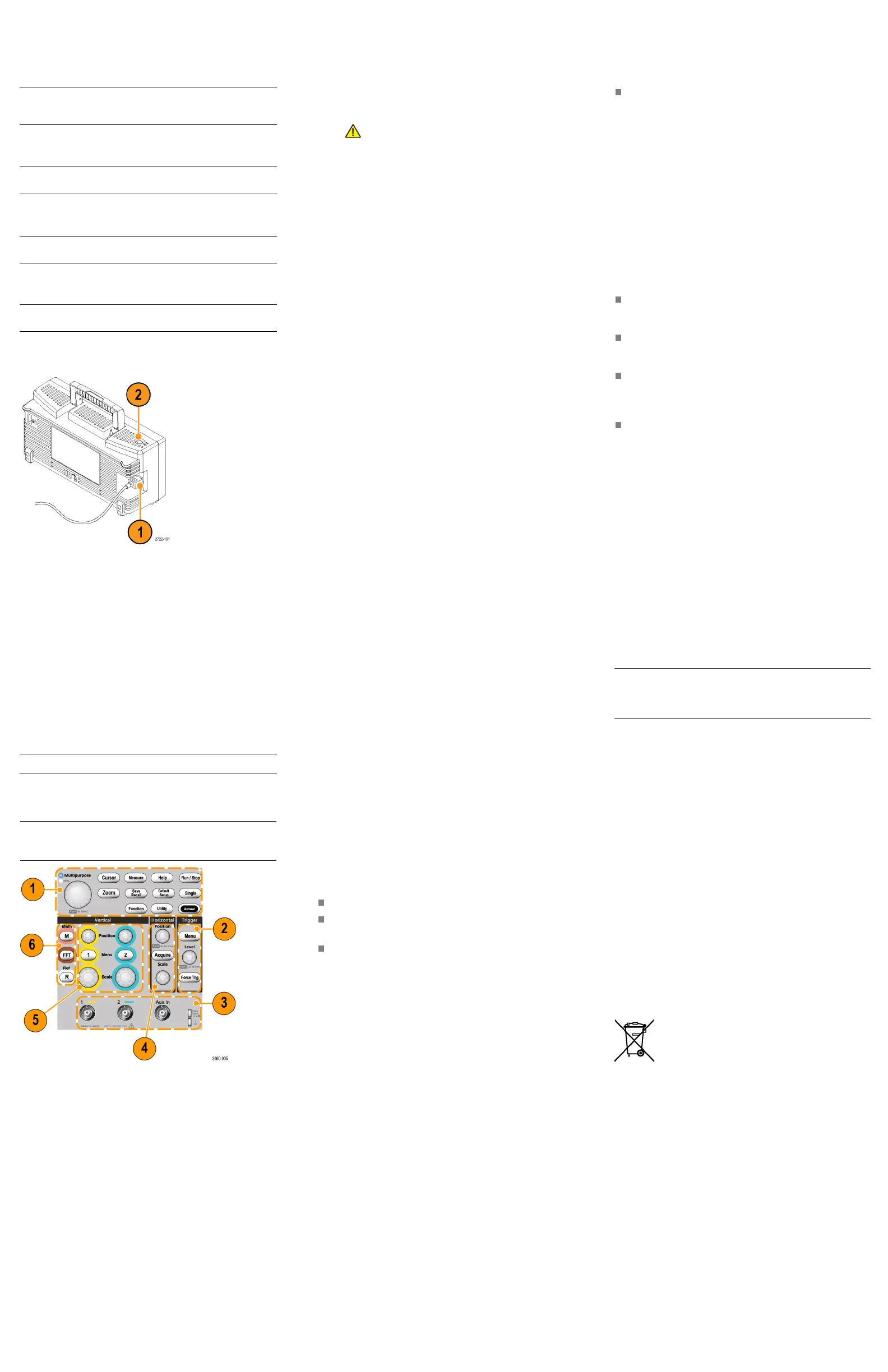
Front panel
NOTE. Some control and connector positions are differe nt
between t he two- and four-channel models, but their functions
are the same.
1. Use the Menu and control buttons to select menu items,
set values, display and move cursors, magnify a section of
the waveform and access the embedded help.
2. Use the Tr
igger controls to set the trigger type, source
channel, trigger signal c oupling, the signal’s trigger slope
(positive or negative), trigger level, and more.
3. Use the two probe input BNC connectors to connect the
oscilloscop
e to the signal. The maximum measurement
input voltage is 300 V
RMS
,CATII.
A
symbol next to a m easurement readout indicates a
signal over
range condition (clipping). This is often caused
by waveforms that extend above or below the screen edge.
To get an acc
urate measurement readout, adjust the vertical
scale and/or position knob to show the entire waveform
on the scree
n.
Use the Aux In BNC input to connect an external trigger
source.
Use the probe compensation output and chassis reference
to electrically match a voltage probe to the oscilloscope
input circuit.
4. Use the Hori
zontal controls to position a channel or math
waveform horizontally, set the acquisition mode, set the
waveform re
cord length, set the horizontal scale (time per
major horizontal graticule and samples/second), and more.
5. Use the Vertical controls to select a waveform to display,
open menus to set signal coupling, bandwidth, probe
attenuation and type; move the waveform up or down on
the screen; set the vertical scale factor (volts per vertical
graticule division); and more.
6. Use the Resource controls to display waveform m ath
operations, display FFT spectrum waveforms, or to display
reference memory waveforms.
USB ports
Front panel. Use the front-panel USB port to connect a
flash drive for file storage and retrieval, saving and recalling
instrument setups, and to perform firmware upgrades.
Rear panel. Use the USB Device port to connect to a PC for
remote control using USBTMC protocol.
Cleaning
Use a dry, soft cotton cloth to clean the outside of the unit.
Do not use any liquid cleaning agents or chemicals that could
damage the case, controls, screen, markings or labels, or
possibly infiltrate the case.
Compliance
This sect
ion lists the EMC (electromagnetic compliance),
safety, and environmental standards with which the instrument
complies
. This product is intended for use by professional and
trained personnel only; it is not designed for use in households
or by chil
dren.
Questions about he following compliance information may be
directed to the following address:
Tektronix, Inc.
PO Box 500, MS 19‐045
Beaverton, OR 97077, USA
www.tek.com
EMC com pliance
EU EMC Directive
Meets intent of Directive 2014/30/EC for Electromagnetic
Compatibility. Compliance was demonstrated to the following
specifications as listed in the Official Journal of t he European
Communities:
EN 61326-1, EN 61326-2-1. EMC requirements for electrical
equipment for measurement, control, and laboratory use.
123
45
CISPR 11 (Group 1, Class A)
IEC 61000-4-2; IEC 61000-4-3; IEC 61000-4-4;
IEC 6100
0-4-5; IEC 61000-4-6; IEC 61000-4-11
EN 61000-3-2:A1/A2; EN 61000-3-3
1
This product is intended for use in nonresidential areas only. Use in residential
areas may cause electromagnetic interference.
2
Emissio
ns that exc eed the levels required by this standard may occur when
this equipment is connected to a test object.
3
Equipment may not meet the immunity requirements of applicable listed
standards when test leads and/or test probes are connected.
4
For compliance with the EMC standards listed here, high quality shielded
interface cables that incorporate low impedance connection between the cable
shield and the connector shell should be used.
5
10 mV/division to 1 V/division: ≤1.0 division waveform displacement or
≤2.0 di
vision increase in peak-to-peak noise is allowed when the instrument
is subjected to fields and signals as defined in the IEC 61000-4-3 and
IEC 610
00-4-6 tests.
Australia / Ne w Zealand declaration of conformity – EMC
Complies with the EMC provision of the Radiocommunications
Act per the following standard, in accordance with A CMA:
CISPR 11. Radiated and Conducted Emissions, Group
1, Class A, in accordance with EN 61326-1 and EN
61326-2-1.
FCC – EMC
Emissions are within the limits of FCC 47 CFR, Part 15,
Subpart B for Class A equipment.
Safety compliance
This section lists the safety standards with which the product
complies and other safety compliance information.
EU Lo w Vo ltage Directive
Compliance w as demonstrated to the following speci fi cation as
listed in the Official Journal of the European Union:
Low Voltage Directive 2014/35/EU.
EN 61010-1; EN 61
010-2-030
U.S. nationally recognized testing laboratory listing
UL 61010-1; UL 61010-2-030
Canadian certification
CAN/CSA-C22.2 No. 61010-1; CAN/CSA-C22.2 No.
61010-2-030
Additional compliances
IEC 61010-1; IEC 61010-2-030
Equipment type
Test and measuring equipment.
Safety class
Class 1 - grounded product.
Pollution degree rating
Pollution Degree 2 (as defined in IEC 61010-1). Rated for
indoor, dry location use only.
Measurement and overvoltage category descriptions
Measurement terminals on this product may be rated for
measuring mains voltages from one or more of the following
categories (see specific ratings marked on the product and in
the manual).
Category II. Circuits directly connected to the building wiring
at utilization poin
ts (socket outlets and similar points).
NOTE. Only measurement circuits have a measurement
category rating. On
ly mains power supply c ircuits have an
overvoltage category rating. Other circuits within the product
do not have either ra
ting.
Mains overvoltage category rating
Overvoltage catego
ry II (as defined in IEC 61010-1).
Environmental considerations
This section provides information about the environmental
impact of the product.
Restriction of hazardous substances
Complies with RoHS2 Directive 2011/65/EU.
Product end-of-life handling
Observe the following guidelines when recycling an instrument
or component:
Equipment recycling . Production of this equipment required
the extraction and use of natural resources. The equipment may
contain substances that could be harmful to the environment or
human health if improperly handled at the product’s end of life.
To avoid release of such substances into the environment and
to reduce the use of natural resources, we encourage you to
recycle this product in an appropriate system that will ensure
that most of the materials are reused or recycled appropriately.
This symbol indicates that this product complies
with the applicable European Union requirements
according to Directives 2012/19/EU and
2006/66/EC on waste electrical and electronic
equipment (WEEE) and batteries. For information
about recycling options, check the Tektronix Web
site (www.tek.com/productrecycling).
Battery recycling. This product contains a small installed
lithium metal button cell. Please properly dispose of or
recycle the cell at its end of life according to local government
regulations.
Perchlorate materials. This product contains one or
more type CR lithium batteries. According to the
state of California, lithium batteries are classified as
perchlorate materials and require special handling. See
www.dtsc.ca.gov/hazardouswaste/perchlorate for additional
information.
Copyright © Tektronix, Inc. All rights reserved. www.tek.com