Maintenance
TDS1000B and TDS2000B Series Oscilloscope Service Manual
6-- 33
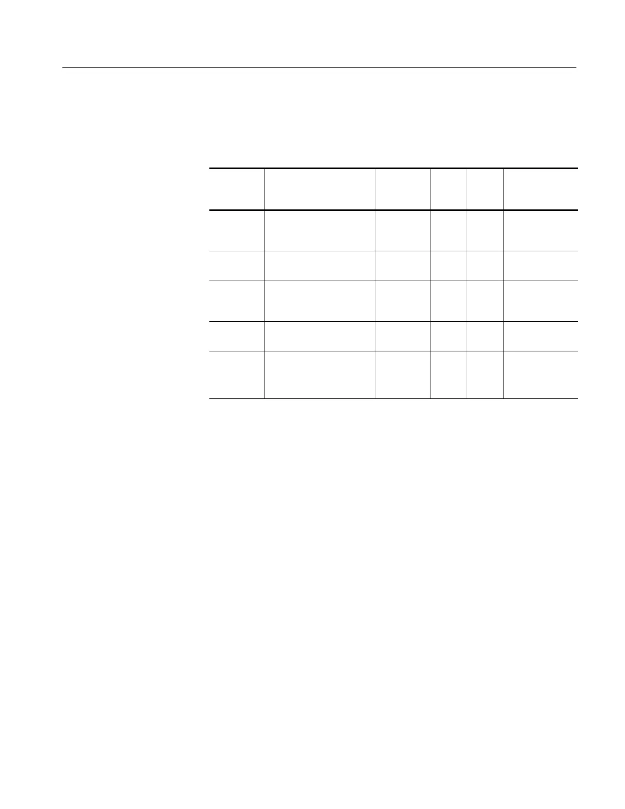
2. Use the test oscilloscope to measure the voltages from the power supply
module at J101 on the main board module. The table below lists the voltages
you should expect to see.
Supply Voltage range*
Maximum
current
draw
J101
power
pins
J101
return
pins
Derived
supplies
35 V 30 V
DC
to 40 V
DC
floating.
Pin 2 connected to +3.3 V
on the main board.
15 mA 1 2 +28 V LCD
+6 V 5.5 V to 6.5 V 0.7 A 4 3, 5, 8,
10
+5 V
+3.3 V 3.0 V to 3.6 V. Requires
minimum load to maintain
regulation.
1.5 A 6, 7 3, 5, 8,
10
3.3 V, +2.5 V
-- 4 V -- 5 . 0 V t o -- 3 . 5 V 0.8 A 9 3, 5, 8,
10
-- 2 . 5 V
Line trigger --2 V to 6 V open circuit.
±1 diode drop when at-
tached to the main board.
1mA 11 3, 5, 8,
10
Line trigger
*
With 3 W minimum load; still functions with no load.
3. If all of the voltages are present, the main board is probably defective.
Replace it.
The oscilloscope runs an extensive self-diagnostic routine at every power-on.
Running the diagnostics from the Service menu will provide no additional
information and therefore is not needed. The menu selections are only used
during manufacturing of the oscilloscope.
Follow these steps to troubleshoot the input connections only if the oscilloscope
appears to function normally in every way. However, you have determined that
an input signal is not getting into the oscilloscope as expected.
1. Remove the rear case using the procedure Rear Case on page 6--9.
2. Check that the coaxial connections to the back side of the BNC connectors
are intact. Use the DMM to measure continuity from the front side of the
BNC connector to the point where it attaches to the Main board.
Running Diagnostics
Troubleshooting Input
Connections
 Loading...

