Portable Mainframe Removal and Installation Procedures
12
TLA7000 Series Mainframe Technical Reference Manual
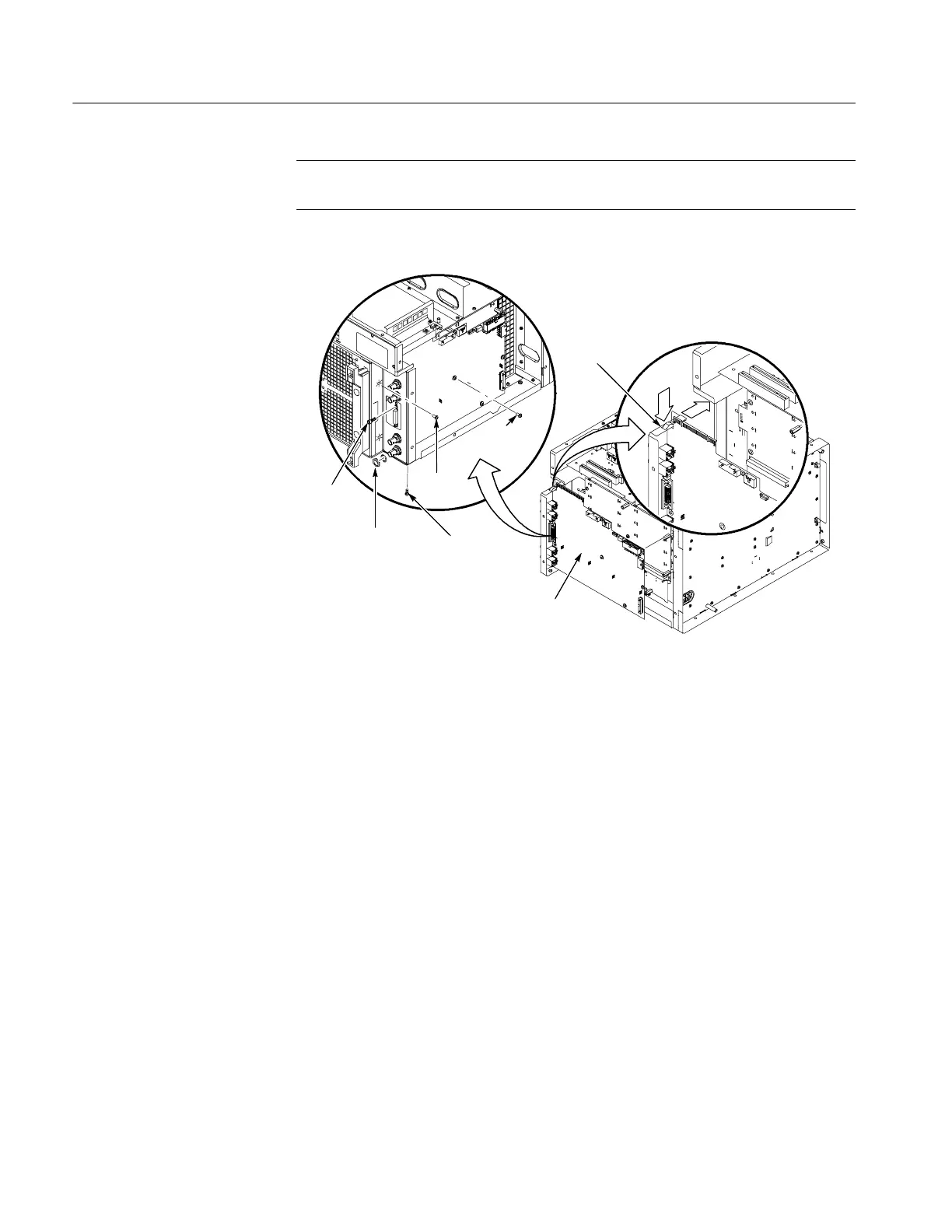
NOTE. When installing the BNC nuts and the two jack screws, tighten them to
12 in-lbs ±1.5 in-lbs.
Screws (2)
Jack
screws (2)
Screw (1)
BNC nuts and
washers (4)
Screws (5)
To install, press
downonEMIclipto
prevent damage to
ground fingers.
Interface board
assembly
Figure 7: Removing the inter face board
Backplane
Complete the following steps to remove the backplane. Refer to Figure 24 on
page 45 for the detailed exploded view drawings. Installation procedures are the
reverse of the removal procedures.
1. Remove the instrument covers. (See Instrument Covers on page 6.)
2. Remove the top EMI cover. (Refer to Figure 22 on page 41.)
3. Remove the interface board. (See Interface Board on page 11.)
4. Gently remove the interface board from the backplane board.
5. Remove the four screws and four binding posts from the backplane board.
6. Slide the backplane under the chassis post as indicated in Figure 8 on
page 13.
7. Pull out the backplane.
 Loading...


