Benchtop Mainframe Removal and Installation Procedures
26
TLA7000 Series Mainframe Technical Reference Manual
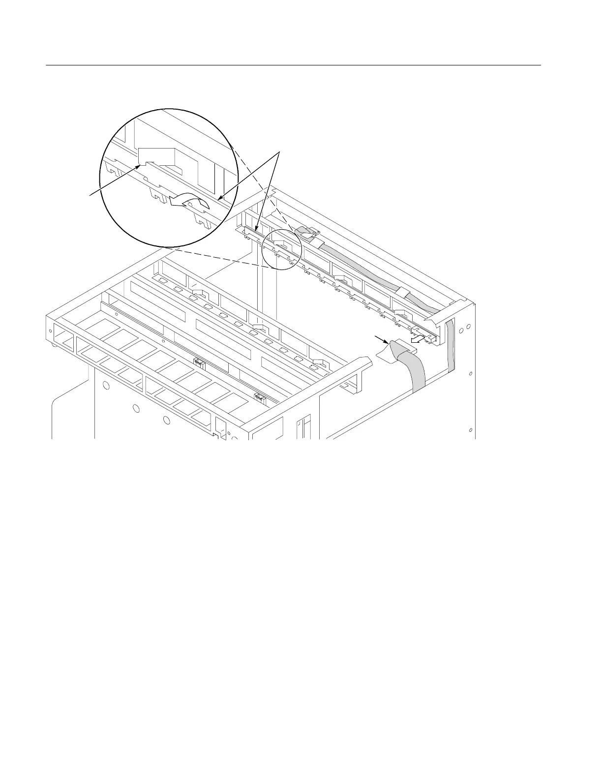
Cable
Retainer
Temperature
sense board
Figure 16: Removing the t emperature sense board
Front Panel and Display Module
Perform the following steps to replace the front panel and display module:
1. Remove the mainframe cover by following the Mainframe Cover removal
procedure on page 22.
2. Note the orientation of the power switch. (The green LED is toward the
front-left side; see F igure 17).
3. Using needle-nose pliers, remove the five wires from the power switch. (The
color-coded connections are shown later in the installation procedure).
4. Remove the two T-7 screws from the front panel and remove the front panel.
 Loading...


