Theory of Operation
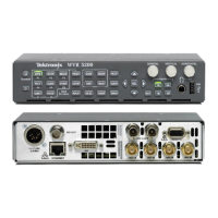
Front Panel
The front panel contains a small processor that communicates to the control
processor through RS232 signaling. Power, ground, fault and a programming
signals allow the front panel processor flash code to be updated.
LTC
LTC signals are routed to the decoder chip. The control processor reads the time
values from the decoder chip. If selected by the user, the decoded time values can
be display
ed on the XGA monitor and used to time stamp alarm log entries.
LTC inputs come from the remote connector. The LTC signal is also applied to
an A/D con
verter and then input to the waveform processing FPGA to create the
LTC waveform display.
NOTE. The FPGA’s decode VITC s ignals digitally.
Audio O
ption Board
The audio option (if installed) resides on the upper "mezzanine" board.
Therearetwoaudiooptions:
Option AD adds support for Analog audio and Digital audio monitoring
Option DDE adds support for Dolby E decode, Dolby Digital (AC-3) decode,
and Analog/Digital audio monitoring
Table 2-1: Supported audio options
Order this kit
To add this option
to a previously
purchased
instrument WVR6020 WVR7020 WVR7120
AD WVR6UP-AD WVR70UP-AD WVR7UP-AD
DDE WVR6UP-DDE not supported WVR7UP-DDE
WVR6020, WVR7020, and WVR7120 Waveform Rasterizers Service Manual 2–5

 Loading...


