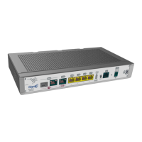
C Eth WAN-2 Base-T. WAN 2.5 Gigabit Ethernet.
For more information about the WAN interface, please refer to:
- WAN 2.5G connection on page 17
- WAN Base-T connectors on page 30
- WAN Base-T interface on page 32
D 4-port Gigabit Ethernet Switch (LAN1 to LAN4).
For more information on the LAN interface, please see:
- 4-port Ethernet switch connections on page 16
- LAN connectors on page 29
- LAN interface on page 32
E LED PWR (Power). Please fefer to on page for more information.
F LED WLAN (WLAN Status). Please refer to LEDs on page 7 for more information.
G RST. Reset button. To understand how the reset button works, please refer to
RST button on page 15.
H Aux. Grants access to the Teldat M2 local console, allowing for configuration and
monitoring purposes.
To learn more about the Aux connector, please consult:
- Connecting for configuration on page 20
- Configuration connector on page 31
- Configuration interface on page 35
I Power source connection (DC IN).
Please refer to Power source on page 14 for information regarding Power connec-
tion and Power supply on page 35 for power specifications applicable to theTeld-
at M2 device.
J Kensington security slot
For additional details, kindly refer to on page
K xDSL interface.
For detailed information about the xDSL interface, please refer to:
- xDSL connection on page 19
- xDSL connector on page 31
- xDSL interface on page 35
Furthermore, the front panel features LEDs that correspond to the LAN and WAN Ethernet interfaces.
3.1.1.1 LEDs
The following figure shows the router's WAN-1 LED indicators:
Teldat
3 Components and Power Supply
Teldat M2/M2L 7
 Loading...