Manual Door intercom devices a / b series 20 / 30 / 40 / 50 / 20-0028A/-0028B
Connection
GB
61www.behnke-online.com
Please note: You can find further
configuration steps from page 72 onwards.
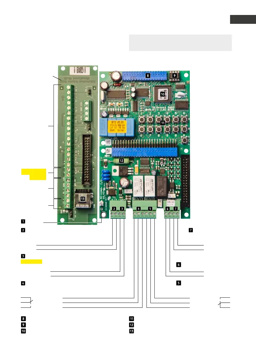
6 - 24 V =
Alarm input
–
+
Relay 2
Relay switching power: max. 60 VA
24 W 0.5 A 120 V~ or 1A 24V=
Make contact
Control contact
Rest contact
Universal electronics 20-0005
Connection for additional boards
EEprom
Master CPU
Sub circuit
board *
Suitable
Installation
material for
adaptation of
speaker, micro-
phone and buttons
at the door: branch-
off box 20-9251
Clamps
buttons 1 to 8
potential-free
buttons, max. 25 m
cable length
(cf. Seite 50)
(configuration
steps 21 to 28)
Microphone
(Maintain the
polarity!)
not in use
Speakers
Internal configuration keyboard
Heating resistor
Connection socket for number keypad max.
25 m connection cable 20-9308 (3 m)
Earthing
Telephone line
Main analogue connection or
analogue extension of a telephone system
Wire a
Wire b
12 - 15 V =
Additional power supply
potential-free voltage
e.g. from a Behnke power supply unit
–
+
Relay 1
Relay switch power: max. 60 VA/24 W:
0,5 A 120 V~ or 1A 24V=
Rest contact
Control contact
Make contact
Video output
only connected with a
module with camera
Video signal
Video mass
 Loading...