GB
Manual Door intercom devices a / b series 20 / 30 / 40 / 50 / 20-0028A/-0028B
Connection
GB
60 www.behnke-online.com
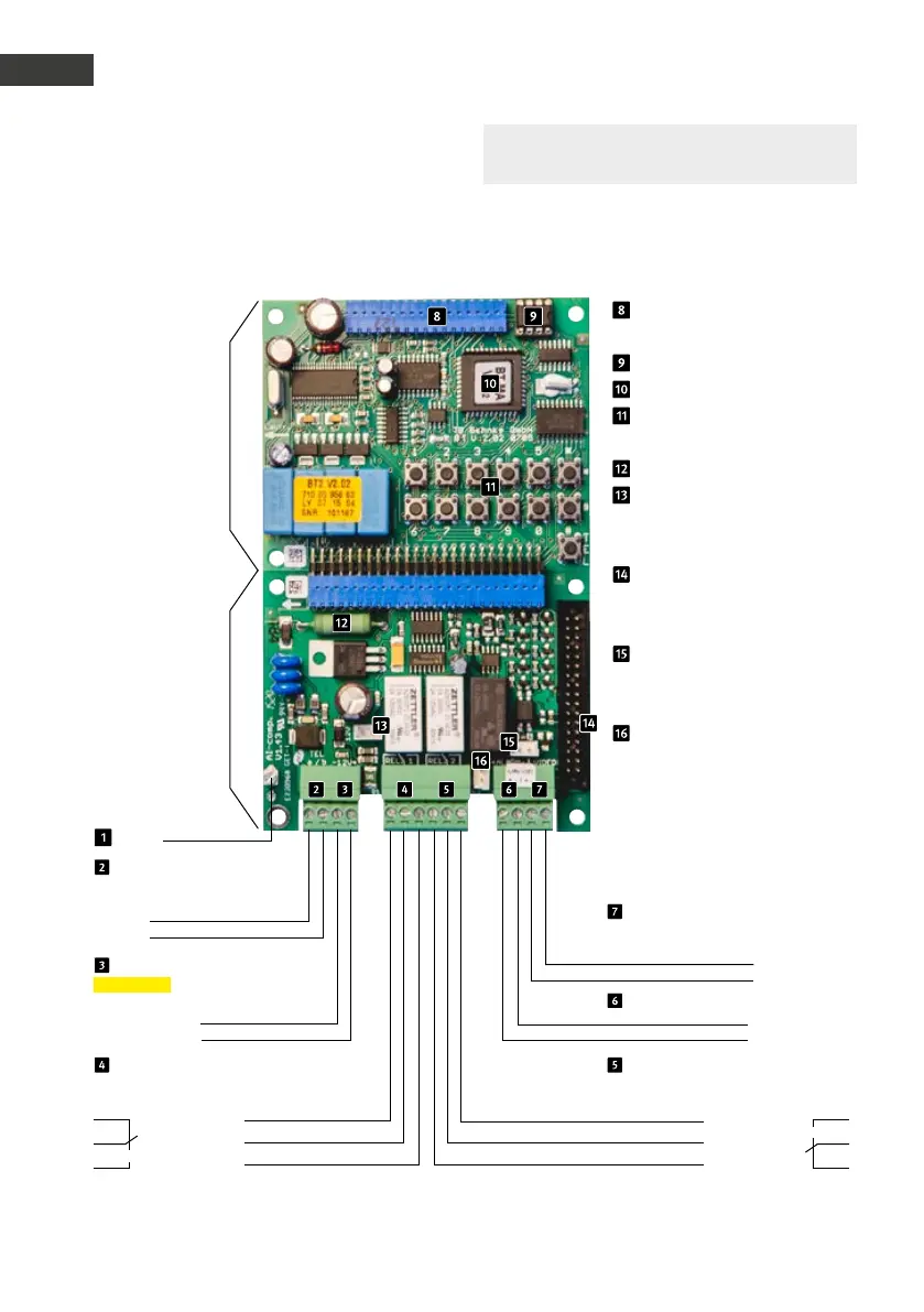
3.1. Wiring diagrams
Compact electronics 20-0001/-0002/-0010
*
/-0013/-0014/-0016/-0041/-0043
Connection for
additional boards
EEprom
Master CPU
Internal configuration key-
board
Heating resistor
Connector for lighting (only
required for modules with
lighting)
Flat ribbon line for connect-
ing modules with buttons,
speakers, microphone, etc.
Alarm input only for turning
off the Behnke wide angle
IP camera with app function
Relay 2 only for turning on
the Behnke wide angle IP
camera with app function
Main board
Connection
board
Earthing
Telephone line
Main analogue connection or analogue
extension of a telephone system
Video output
only connected with one module
with camera
Wire a
Video signal
Wire b
Video mass
12 - 15 V =
6 - 24 V =
Additional power supply
potential-free voltage
e.g. from a Behnke power supply unit
Alarm input
–
–
+
+
Relay 1
Relay switch power: max. 60 VA/24 W:
0,5 A 120 V~ or 1A 24V=
Relay 2
Relay switching power: max. 60 VA 24 W
0.5 A 120 V~ or 1A 24V=
Rest contact Make contact
Control contact Control contact
Make contact Rest contact
Please note: You can find further
configuration steps from page 72 onwards.
* Connector for 20-0010 cannot be removed
 Loading...