200
R36
200
R37
200
R38
200
R39
200
R40
200
R35
200
R34
7P
6P
5P
4P
3P
2P
1P
BAT-
1 2
3 4
5 6
7 8
9 10
11 12
13 14
15
17
19
16
18
20
J19
PEC10DAAN
10P
9P
8P
200
R33
200
R32
200
R30
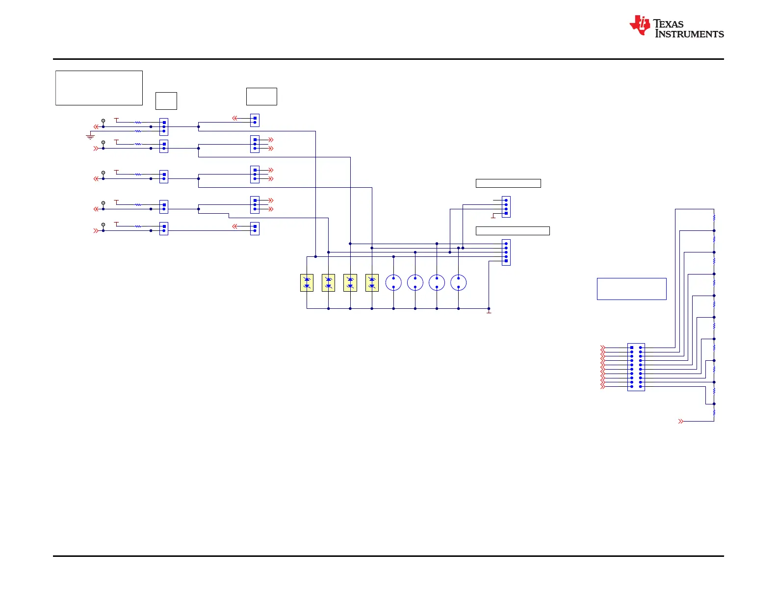
Cell Simulator - Populate
shunts to use cell simulator
if not connecting a battery.
ALERT
SCL
SDA
HDQ
CFETOFF
External I2C Connection
4
1
2
3
J13
PACK-
SDA
SCL
5
4
1
2
3
J18
External SPI Connections / HDQ
SPI_MISO
SPI_MOSI / HDQ
SPI_CLK
SPI_CS
PACK-
PGND
E4E3E2E1
U5U4U3U2
PGND
Multi-function Pins for External Communication
--------------------------------------------------------------
CFETOFF / SPI_CS
HDQ / SPI_MOSI
SDA / SPI_MISO
SCL / SPI_SCLK
ALERT / HDQ
1
2
3
J8
REG1
10k
R28
10k
R29
REG1
REG1
10k
R27
1
2
J9
REG1
10k
R25
VSS
1
2
J11
1
2
J14
1
2
J16
10k
R31
REG1
TP20
TP21
TP22
TP23
TP24
uC_SPI_CS
1
2
3
J10
uC_SPI_MOSI
uC_HDQ
uC_SPI_MISO_A
uC_SDA
uC_SPI_CLK
uC_SCL
uC_HDQ
Pull-up /
pull-down
selection
uController
interface type
selection
1
2
J7
1
2
J17
100k
R26
EXT_SPIMISO_SDA
EXT_SPI_MOSI_HDQ
EXT_SPI_CS
EXT_SPICLK_SCL
1
2
3
J12
1
2
3
J15
Figure 5-10. Schematic Diagram Pin Configuration
BQ76942EVM Circuit Module Physical Construction
www.ti.com
40 BQ76942 Evaluation Module SLUUC32A – NOVEMBER 2019 – REVISED OCTOBER 2020
Submit Document Feedback
Copyright © 2020 Texas Instruments Incorporated

 Loading...


