- 38 -
Configuration error
Invalid timer setting, see page 25
Offset setting = 0 or not defined, see page 26
Feature not available because serial communication
mode is enabled
Unit reaction to warning/fault errors depend on how the unit is configured, see
Setup/Tuning Loop on page 20. The unit is shipped configured to continue
running. If any other code appears contact Thermo customer service.
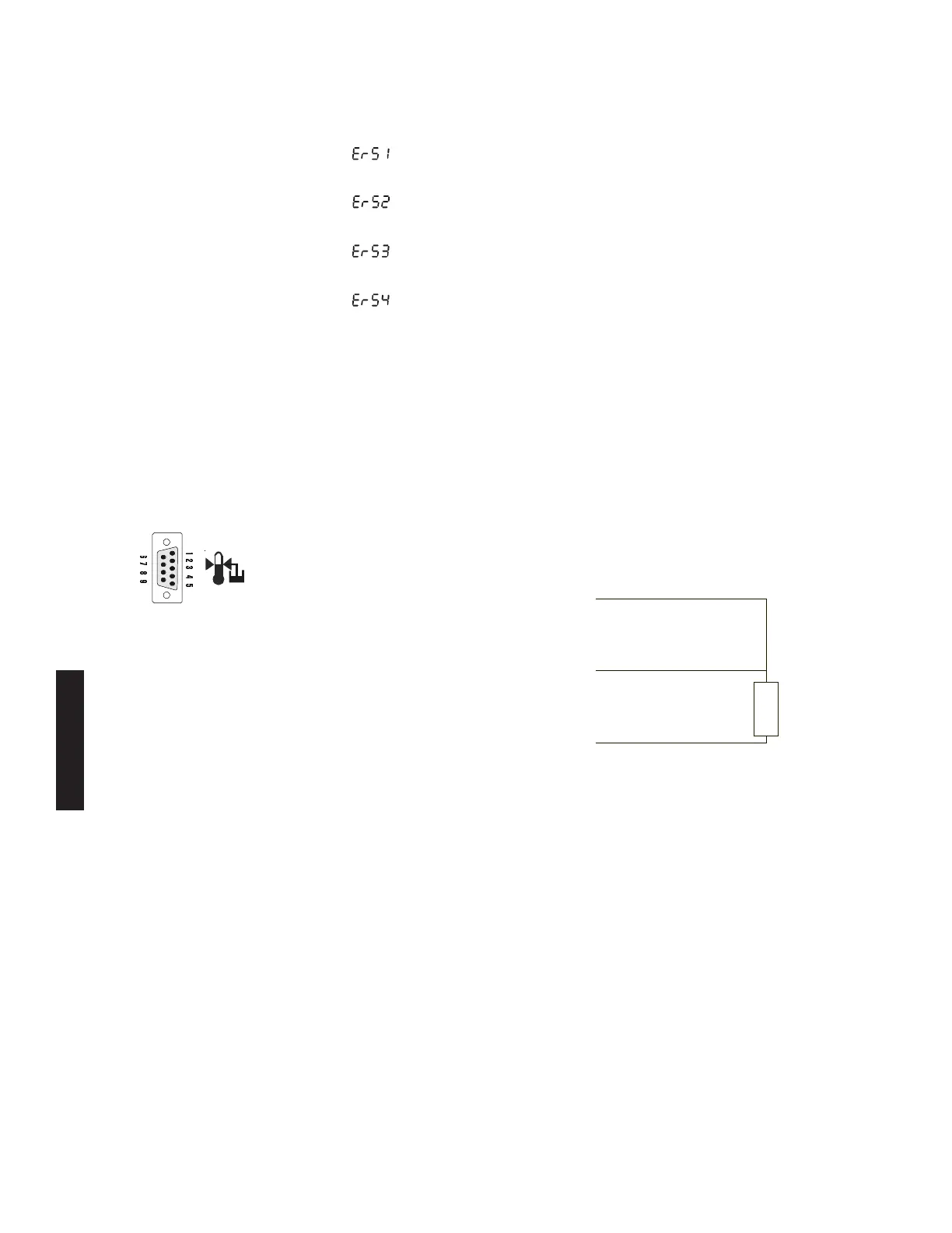
External Sensor
Connector
Digital Plus units are equipped with a male 9-pin D-connector located on the
rear of the control box. The connector is used with an optional external sensor.
Troubleshooting
Pin # Function
1 3-wire RTD connection A
2 No connection
3 No connection
4 3-wire RTD connection A
5 No connection
6 No connection.
7 3-wire RTD connection B
8 No connection
9 No connection
Hardware Internal Connector Mating Connector
AMP Part# 745492-2 AMP Part# 745491-2
RTD
Example
 Loading...