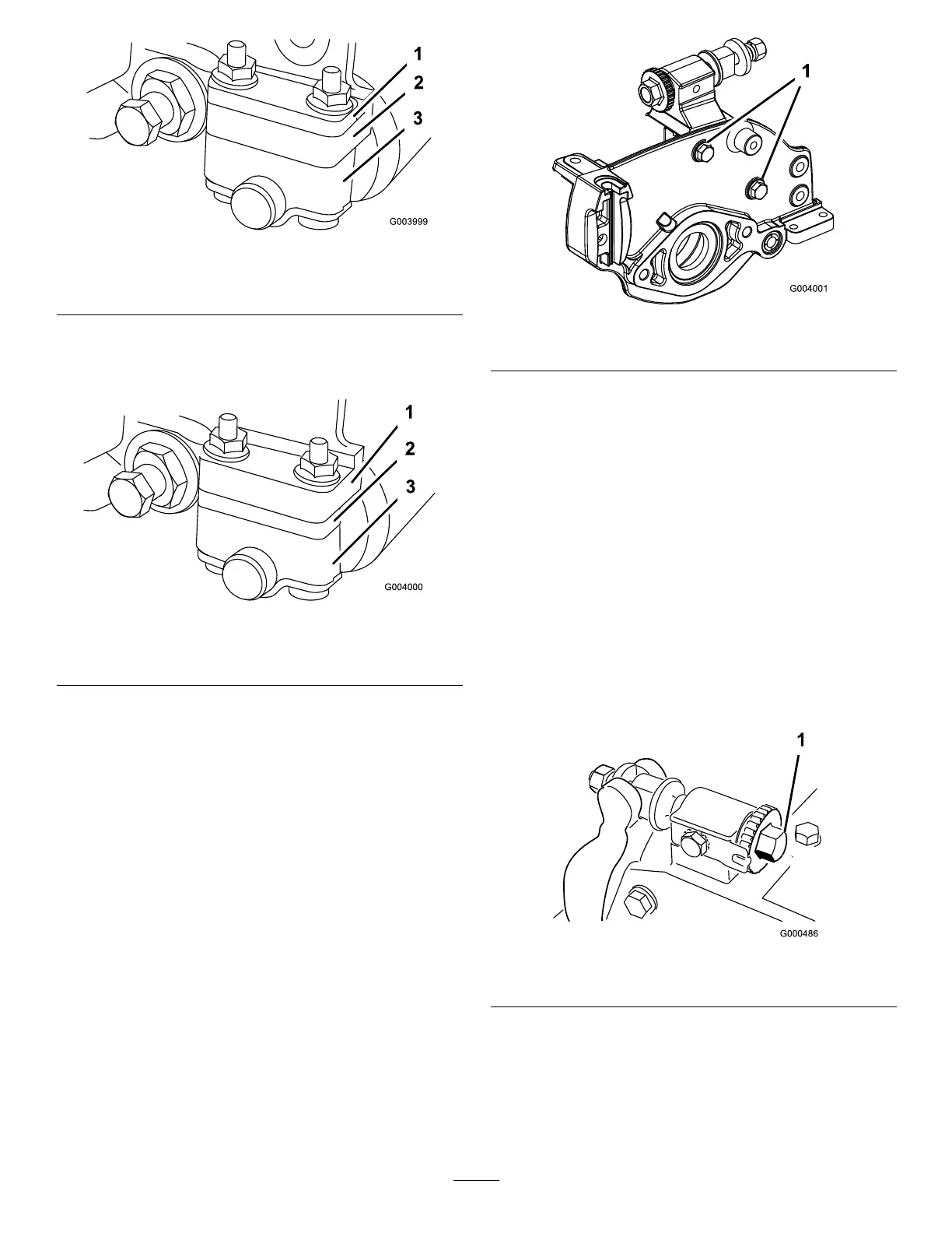
Figure55
1.Spacer
3.Rollerbracket
2.Sideplatemountingange
•Positionthespacerbelowthesideplatemounting
angewhenheightofcutsettingsrangefrom
1/8"to1"(Figure56).
Figure56
1.Sideplatemountingange
3.Rollerbracket
2.Spacer
2.Toadjustrearrollerproceedasfollows:
•Raiserearofcuttingunitandplaceablockunder
bedknife.
•Remove(2)nutssecuringeachrollerbracketand
spacertoeachsideplatemountingange.
•Lowerrollerandscrewsfromsideplatemounting
angesandspacers.
•Placespacersontoscrewsonrollerbrackets.
•Re-securerollerbracketandspacerstounderside
ofsideplatemountingangeswithnuts
previouslyremoved.
3.Verifythatthebedknifetoreelcontactiscorrect.Tip
mowertoexposefrontandrearrollersandbedknife.
Note:Thepositionoftherearrollertothe
reeliscontrolledbythemachiningtolerancesof
theassembledcomponentsandparallelingisnot
required.Alimitedamountofadjustmentispossible
bysettingthecuttingunitonasurfaceplateand
looseningthesideplatemountingbolts(Figure57).
Adjustandre-tightenbolts.
Figure57
1.Sideplatemountingbolts
Important:Wheneverthecuttingunithasto
betippedtoexposebedknife/reel,propuprear
ofcuttingunittomakesurenutsonbackend
ofbedbaradjustingscrewsarenotrestingon
worksurface.
AdjustingtheBedknifetothe
Reel
Bedknifetoreeladjustmentisaccomplishedby
looseningortighteningbedbaradjustingscrews,located
ontopofmower.
1.Positionmachineonaat,levelworksurface.
2.Makesurereelcontactisremovedbyturningbedbar
adjustingscrewscounterclockwise(Figure58).
Figure58
1.Bedbaradjustingscrew
3.Tiltmoweronbacktoexposebedknifeandreel.
4.Atoneendofreel,insertalongstripofnewspaper
betweenreelandbedknife(Figure59).Whileslowly
rotatingreelforward,turnbedbaradjustingscrew
clockwise(onsameendofreel)(Figure58),oneclick
atatime,untilpaperispinchedlightly,wheninserted
32

 Loading...


