5.Whilemaintainingaslightgapbetweenthe
coversealandthesideplate,installeach
mountingboltuntilthethreadsengageinthe
insert.Thegapallowsvisualalignmentofthe
boltstothethreadedinserts.
6.Afterallboltsareinstalled,tightenthemuntil
thestand-offsinsidethecovercontacttheside
plate.Donotovertightenthebolts.
AdjustingthePrimaryV-Belts
1.T oadjustthebelttensiononprimaryV-belts,
rstchecktheadjustmentofthetractioncontrol;
refertoAdjustingtheTractionControl(page
35).Ifyouareunabletoattainthe27to32N(6
to7lb)forcerequiredinadjustingthetraction
control,proceedtothenextstep.
2.LoosentheretainerthatsecurestheV-beltcover
andpivotthecoveropen(Figure46).
g016991
Figure46
1.V-beltcover2.Retainer
3.T oincreasethebelttension,loosentheengine
mountingboltsandmovetheenginebackwards
intheslots.
Important:Donotover-tensionthebelt.
4.Tightenthemountingbolts.
Note:Thedistancebetweenthecenterofthe
drivepulleyandthecenterofthedrivenpulley
shouldbeapproximately12.9cm(5.1inches)
afterthenewV-beltsareinstalled.
5.AftertensioningtheprimaryV-belts,checkthe
alignmentoftheengineoutput-shaftpulleyand
thecounter-shaftpulleywithastraightedge.
6.Ifthepulleysaremisaligned,loosenthescrews
thatsecuretheenginemountingbasetothe
machineframeandslidetheenginefromsideto
sideuntilthepulleysarealignedwithin0.7mm
(0.030inch).
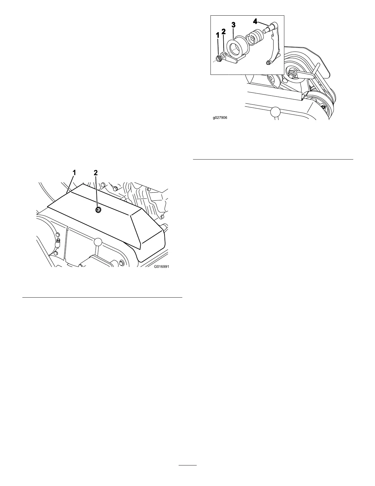
g027906
Figure47
1.Locknut3.Idlerpulley
2.Beltguide4.Idlerarm
7.Tightenthemountingscrewsandcheckthe
alignment.
8.T opushorpullthemachineeasierwithout
startingtheengine,adjustthebeltguide(Figure
47,inset)asfollows:
A.Engagetheclutch.
B.Loosenthelocknutthatsecurestheidler
pulleyandthebeltguidetotheidlerarm.
C.Rotatethebeltguideclockwiseuntilagap
ofapproximately1.5mm(0.06inch)is
obtainedbetweentheguidengerandthe
backsideofthedrivebelts.
D.Tightenthelocknutthatsecurestheidler
pulleyandthebeltguidetotheidlerarm.
9.Closethecoverandsecuretheretainer.
ReplacingtheDifferential
Belt
1.Removetheboltsthatsecurethetractiondrive
andreel-drivebeltcoverstotherightsideplate
andremovethebeltcovers.
2.Loosentheidlerpulleymountingnuton
eachidlerpulleyandpivoteachidlerpulley
counterclockwiseawayfromthebacksideof
eachbelttoreleasethebelttension.
3.Removethebelts.
4.Removetheboltsthatsecurethefrontand
rearsectionsofthedifferentialcovertothe
differentialhousingandslidethecoversections
awaytoexposethebelt(Figure48).
34

 Loading...


