Note:Theamountofforceneededtocompressthe
leverincreasesnoticeablywhenyouremovetheslack
fromtheauger/impellerdrivebelt(approximately1/2
ofthelevermovement).Theadjustmentiscorrect
whentheforcebeginstoincreaseandthedistance
betweenthetopofthehandgripandthebottomofthe
auger/impellerdrivecontrolleveris1to2inches(3to
5cm)asshowninFigure9.
5.Toadjustthedistance:
A.Removetheclevispin.
B.Loosenthejamnut.
C.Threadtheclevisupordowntoincreaseor
decreasethedistancebetweenthetopofthe
handgripandthebottomoftheauger/impeller
drivecontrollever(
Figure8).
6.Whentheadjustmentiscorrect,installtheclevispin
andsecureitinplacewiththecotterpin(Figure8).
7.Tightenthejamnuttosecuretheclevis(Figure8).
5
InstallingtheChuteControl
Rod
Partsneededforthisprocedure:
1
Chutecontrolrodassembly(rodandbracket,worm
gear,andbracket)
1Bellevillewasher
2Bolt
1
Carriagebolt
3Locknut
1
Curvedwasher
Procedure
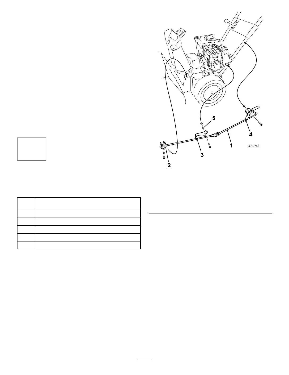
1.Securetheupperchutecontrolbracket(attachedtothe
chutecontrolrod)totheupperleftsideofthehandle
withaboltandalocknut
Figure10.
Figure10
1.Chutecontrolrod
4.Upperchutecontrol
bracket
2.Wormgear,bracket,and
mountingange
5.Curvedwasher
3.Lowerchutecontrol
bracket
Note:Leavethelocknutloose.
2.Securethelowerchutecontrolbracket(attachedtothe
chutecontrolrod)tothelowerleftsideofthehandle
withabolt,acurvedwasher,aatwasher,andalocknut
(Figure10).
Note:Thebracketshouldbefastenedontheoutside
ofthehandle,andtherodshouldbeapproximately
paralleltothegroundandnottouchthehandle.
Note:Leavethelocknutloose.
3.ApplyNo.2generalpurposegreasetothewormgear
(
Figure11).
12
 Loading...