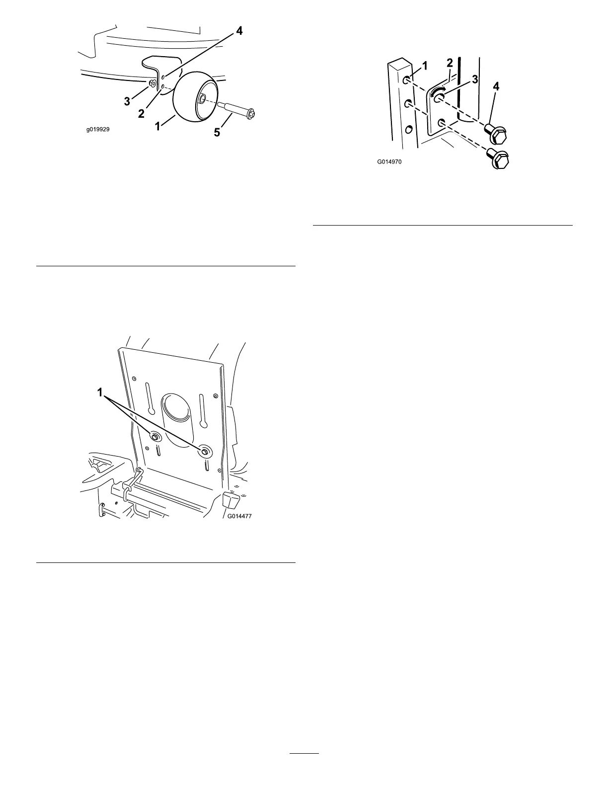
Figure22
1.Anti-scalproller4.Upperhole—themower
deckinthe63mm
(2-1/2inch)andbelow
height-of-cutpositions
2.Lowerhole—themower
deckinthe76mm(3inch)
andaboveheight-of-cut
positions
5.Bolt
3.FlangeNut
PositioningtheSeat
1.Raisetheseatandloosentheadjustmentboltsjust
enoughthatseatcanmove(Figure23).
Figure23
1.Adjustmentbolt
2.Movetheseattothedesiredpositionandtightenthe
bolts.
AdjustingtheMotionControl
Levers
AdjustingtheHeight
Themotioncontrolleverscanbeadjustedhigherorlowerfor
maximumoperatorcomfort.
1.Removethe2boltsholdingthecontrollevertothe
controlarmshaft(Figure24).
2.Movethecontrollevertothenextsetofholes.Secure
theleverwiththe2bolts(Figure24).
Figure24
1.Controlarmshaft3.Slotted,upperhole
2.Controllever
4.Bolt
3.Repeattheadjustmentfortheoppositecontrollever.
AdjustingtheTilt
Themotioncontrolleverscanbetiltedforeoraftfor
maximumoperatorcomfort.
1.Loosentheupperboltholdingthecontrollevertothe
controlarmshaft.
2.Loosenthelowerboltjustenoughtopivotthecontrol
leverforeoraft(
Figure24).Tightenbothboltsto
securethecontrolinthenewposition.
3.Repeattheadjustmentfortheoppositecontrollever.
PushingtheMachinebyHand
Important:Alwayspushthemachinebyhand.Never
towthemachinebecausedamagemayoccur.
Thismachinehasanelectricbrakemechanismandtopush
themachinetheignitionkeyneedstobeintheRunposition.
Thebatteryneedstobechargedandfunctioningforthe
electricbraketobedisengage.
ToPushtheMachine
1.Parkthemachineonalevelsurfaceanddisengagethe
bladecontrolswitch.
2.Movethemotioncontrolleversoutwardtopark
position,stoptheengine,andwaitforallmovingparts
tostopbeforeleavingtheoperatingposition.
3.Locatethebypassleversontheframeonbothsidesof
theengine.
4.Movethebypassleversforwardthroughthekeyhole
anddowntolocktheminplaceasshowninFigure25.
Ensurethisisdoneforeachlever.
5.Movethemotioncontrolleversinwardtotheneutral
positionandturntheignitionkeytotherunposition.
Donotstartthemachine.
21
 Loading...