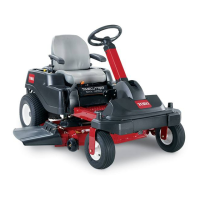
3.Measurefromthetipofthebladetotheat
surface(Figure44).
g014973
Figure44
1.Blade(inpositionformeasuring)
2.Levelsurface
3.Measureddistancebetweenbladeandthesurface(A)
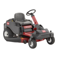
4.Rotatethesameblade180degrees,sothat
theopposingcuttingedgeisnowinthesame
position(Figure45).
g014974
Figure45
1.Blade(sidepreviouslymeasured)
2.Measurement(positionusedpreviously)
3.Opposingsideofbladebeingmovedintomeasurement
position
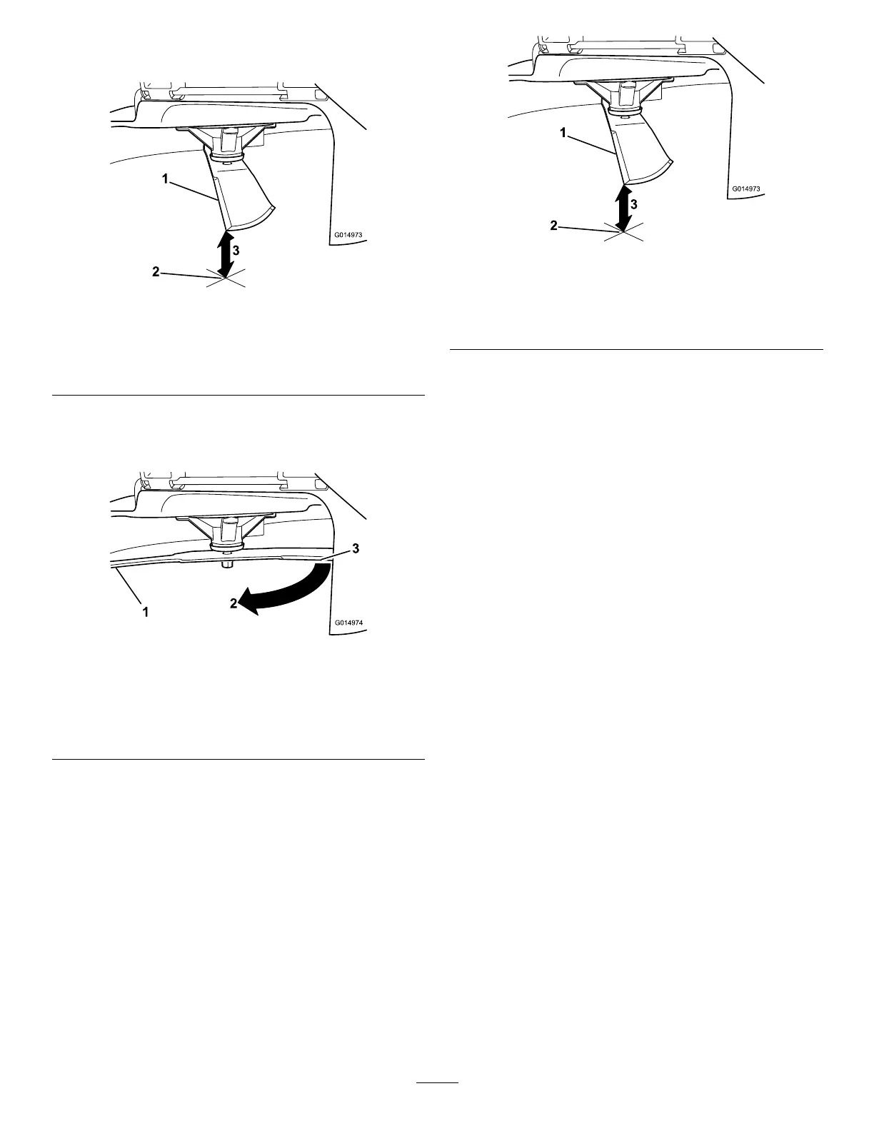
5.Measurefromthetipofthebladetotheat
surface(Figure46).
Note:Thevarianceshouldbenomorethan
3mm(1/8inch).
g014973
Figure46
1.Oppositebladeedge(inpositionformeasuring)
2.Levelsurface
3.Secondmeasureddistancebetweenbladeandsurface(B)
A.IfthedifferencebetweenAandBisgreater
than3mm(1/8inch),replacethebladewith
anewblade;refertoRemovingtheBlades
(page41).
Note:Ifabentbladeisreplacedwithanew
one,andthedimensionobtainedcontinues
toexceed3mm(1/8inch),thebladespindle
couldbebent.ContactanAuthorizedToro
Dealerforservice.
B.Ifthevarianceiswithinconstraints,moveto
thenextblade.
Repeatthisprocedureoneachblade.
RemovingtheBlades
Thebladesmustbereplacedifasolidobjectishit,if
thebladeisoutofbalance,orifthebladeisbent.To
ensureoptimumperformanceandcontinuedsafety
conformanceofthemachine,usegenuineT oro
replacementblades.Replacementbladesmadeby
othermanufacturersmayresultinnon-conformance
withsafetystandards.
1.Holdthebladeendusingaragorthickly-padded
glove.
2.Removethebladebolt,curvedwasher,and
bladefromthespindleshaft(Figure47).
41
 Loading...