Groundsmaster 4500 --D/4700--D Hydraulic SystemPage 4 -- 95
Removal (Fig. 75)
1. Read the General Precautions for Removing and
Installing Hydraulic System Components at the begin-
ning of the Service and Repairs section of this chapter.
2. To prevent contamination of hydraulic system during
manifold removal, thoroughly clean exterior of HI/LOW
range control manifold.
3. Label all hydraulic lines for assembly purposes.
4. Disconnect hydraulic lines from manifold and put
caps or plugs on open hydraulic lines and fittings.
5. Remove HI/LOW range control manifold from the
frame using Figure 75 as guide.
6. If hydraulic fittings are to be removed from control
manifold, mark fitting orientation to allow correct as-
sembly. Remove fittings from manifold and discard O--
rings.
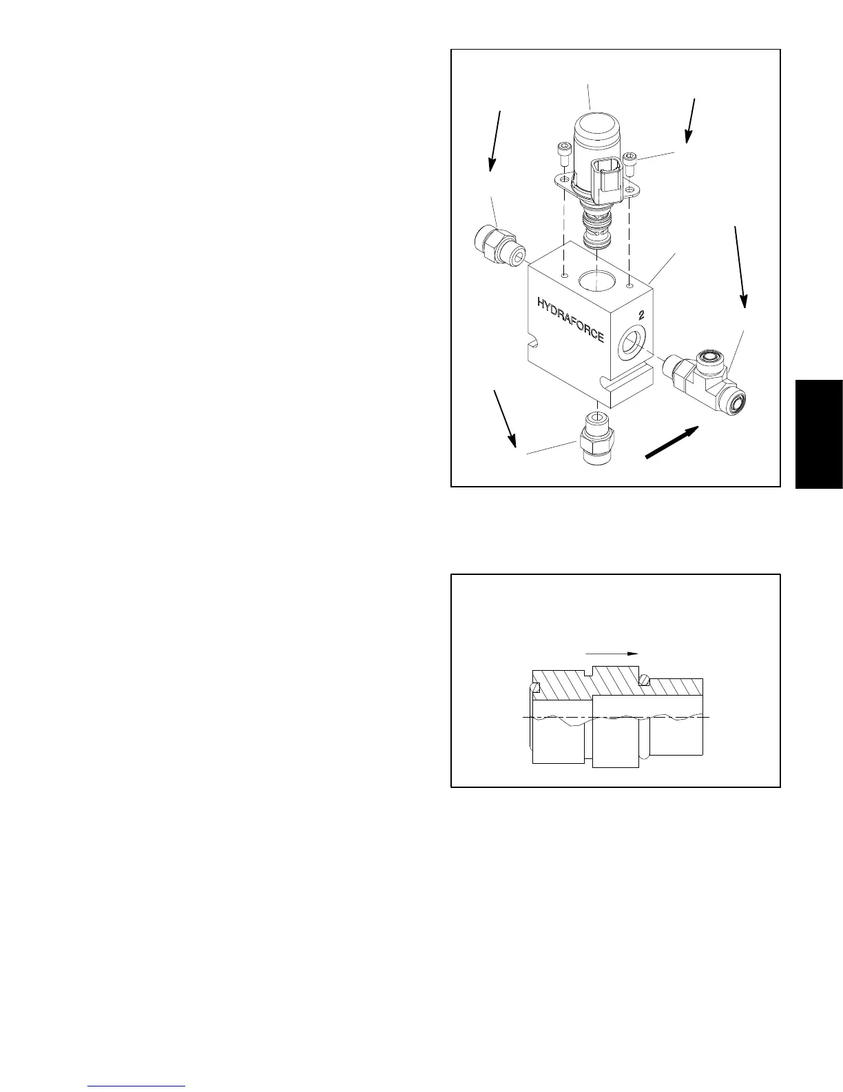
Manifold Service
For cartridge valve service procedures, see Control
Manifold Cartridge Valve Service in this section. Refer
to Figure 76 for cartridge valve and hydraulic fitting
installation torque.
NOTE: The check valve adapter used in the HI/LOW
range control manifold allows free flow toward the mani-
fold and prevents flow away from the manifold (Fig. 77).
Installation (Fig. 75)
1. If fittings were removed from control manifold, lubri-
cate and place new O--rings onto fittings. Install fittings
into manifold ports using marks made during the remov-
al process to properly orientate fittings. Tighten fittings
(see Hydraulic Fitting Installation in the General Infor-
mation section of this chapter).
2. Install HI/LOW range control manifold to the frame
using Figure 75 as guide.
3. Remove caps and plugs from fittings and hydraulic
lines. Using labels placed during manifold removal,
properly connect hydraulic lines to manifold (see Hy-
draulic Hose and Tube Installation in the General Infor-
mation section of this chapter).
4. Fill hydraulic reservoir with hydraulic fluid as re-
quired.
1. Manifold body
2. T ee fitting w/O--ring
3. Straight fitting w/O--ring
4. Check adapter w/O--ring
5. Screw (2 used)
6. Solenoid valve
Figure 76
2
3
6
1
5
4
25 ft--lb
(34 N--m)
30 in--lb
(3.4 N--m)
25 ft--lb
(34 N--m)
25 ft--lb
(34 N--m)
UP
Figure 77
FREE FLOW
CHECK VALVE ADAPTER
Hydraulic
System
 Loading...