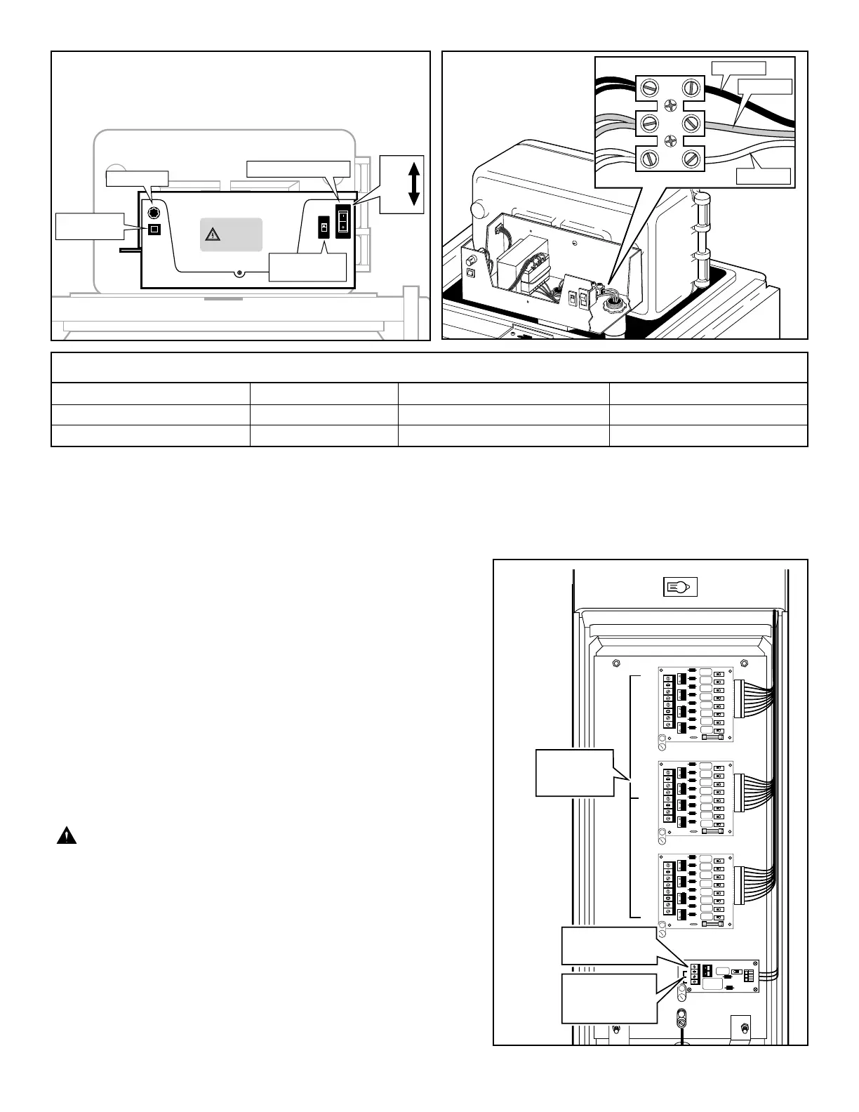
6. Reference Table 1 for the appropriate type of power connection. Secure the wires to the terminal block as indicated in
Figure 4.
7. Reinstall the power supply cover.
8. Apply power to the controller.
Connecting Control Valve Wiring
1. Attach a control wire to one lead of each valve solenoid. Attach a
common wire to the remaining lead of all valve solenoids.
Waterproof all field wire connections using an approved waterproof
splicing method.
2. Label control wires and common wire(s) for identification during
installation. Route the wires through the 2" (51mm) conduit into the
controller cabinet.
3. Secure valve control wires to station terminals in desired operating
sequence. Secure common wire(s) to COM terminals of
pump/common surge module. (Three common terminals are
provided.) See
Figure 5.
Note: The 24-station model is shown in the illustration. Models with
32–48 stations have additional surge modules located on the rear
chassis plate.
All station outputs are labeled with the appropriate station number.
CAUTION: If connecting more than one valve per station,
do not exceed 0.75A (18 VA) maximum.
3
 Loading...