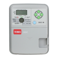
Connecting A Master Valve or Pump Relay
1. Secure a wire pair from the master valve or pump
relay and route it into the satellite pedestal with the
field wires. See Figure 6 for pump relay
configurations.
2. Connect one wire to the pump terminal of the
pump/common surge module.
3. Connect the remaining wire to one of the common
terminals.
CAUTION: Do not connect the pump starter
directly to the controller’s pump start circuit.
Damage to the controller will result. Use a
24 V a.c., 0.75 Amp (max) pump start relay.
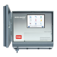
Selecting Operating Mode
The valve station and pump/common surge protection modules
incorporate slide switches which enable three operating modes to
be selected for each valve station. Set switches to the type of
operation mode required:
• AUTO position enables the station circuit to function
automatically per controller operation.
• OFF position disables the station until the switch is moved to
AUTO or ON.
• ON position manually activates the station until the switch is
moved to AUTO or OFF.
CAUTION: When operating stations manually, do not exceed 3.0A maximum current draw. Controller
component damage can result.
Note: The pump/common switch on the surge module controls the pump circuit only – the valve common circuit is not
affected by switch position.
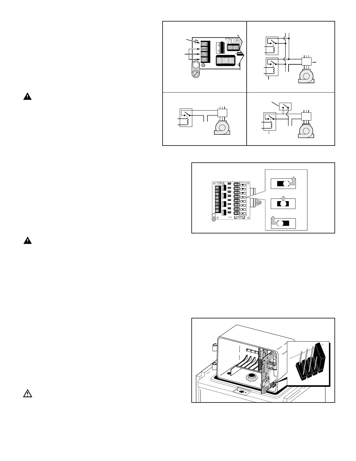
Selecting the Narrow-band Decoder Radio Frequency
Note: Wide-band radio models only – Install the wide band frequency module into the RDR unit at this time. Refer to
Installation Instruction (form number 371-0002) provided with the frequency module for proper installation procedure.
The narrow-band satellite frequency decoder module provides four preprogrammed frequencies, one of which is selected for
use by the placement of a movable jumper located on the module board as shown in
Figure 8.
The pre-programmed frequencies are as follows:
Channel 1=462.2125 Mhz
Channel 2=462.4375 Mhz
Channel 3=467.2125 Mhz
Channel 4=467.4375 Mhz
Note: The decoder module utilizes a programmable frequency
synthesizer which enables each of the preprogrammed
frequencies to be changed as needed for the irrigation site
conditions. Contact your local Toro distributor for additional
information regarding frequency reprogramming.
Important: The base station transmitter, hand-held radio and
frequency decoder module must be set to the same frequency to
enable communication.
4
 Loading...