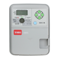
Assigning the Satellite Address Number
Each satellite requires a 3-digit address number to enable
communication with the central controller and/or a hand-held
radio. The address numbers range from 1 (001) through 255 and
are selected using an array of eight DIP switches located on the
frequency decoder module assembly. See
Figure 9. In the down
position, the switch is Off (open) and represents a value of 0
(zero). In the up position, the switch is On (closed) and
represents one of the following binary numbers:
1, 2, 4, 8,16, 32, 64 and 128.
The
wide-band DIP switch array is configured as follows:
Sw 1 = 128 Sw 2 = 64 Sw 3 = 32 Sw 4 = 16
Sw 5 = 8 Sw 6 = 4 Sw 7 = 2 Sw 8 = 1
The narrow-band DIP switch array is configured as follows:
Sw 1 = 1 Sw 2 = 2 Sw 3 = 4 Sw 4 = 8
Sw 5 = 16 Sw 6 = 32 Sw 7 = 64 Sw 8 = 128
To set the satellite address number, place the switch or combination of switches to the On position which provides the
numerical equivalent of the desired address number.
Example for wide-band radio: To set satellite address number 50 (050), start with all eight DIP switches in the Off
(open) position, then close switch numbers 3, 4 and 7; i.e., 32 (Sw 3) +16(Sw 4) +2(Sw 7) = 50. See switch address
code matrix in Table 2.
Example for narrow-band radio: To set satellite address number 50 (050), start with all eight DIP switches in the Off
(open) position, then close switch numbers 2, 5 and 6; i.e., 2 (Sw 2) +16(Sw 5) +32(Sw 6) = 50. See switch address
code matrix in Table 2.
Note: The narrow band satellite utilizes a built-in antenna located on the frequency module assembly. If site conditions are
such that an alternate antenna is required, the optional antenna adapter kit (P/N 102-1204) is required.
Testing Satellite Operation (narrow-band models only)
• Performing a Control Circuit Self Test
A self-test feature is provided to check the functionality of various
key satellite control circuits. Before performing the test, ensure
the Pump/Common module and the Valve Station module
switches are set to the
AUTO position.
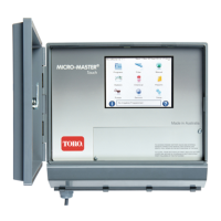
The test is initiated by positioning the TEST/RESET switch, located
on the frequency decoder module, to the TEST position as shown
in
Figure 10. Testing will begin immediately. The test will repeat
continuously until the TEST/RESET switch is positioned to the
center (normal operation) position.
Note: The RESET position resets the frequency decoder
microprocessor to factory defaults. To take affect, the satellite
must be powered up with the switch in the
RESET position. The
switch should be placed in the NORMAL position after 15 seconds of operation.
• Performing a Station Output Test
Ensure the Pump/Common module switch is in the ON position. Position each
Valve Station module switch to the ON position one at a time and confirm
sprinkler operation.
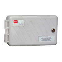
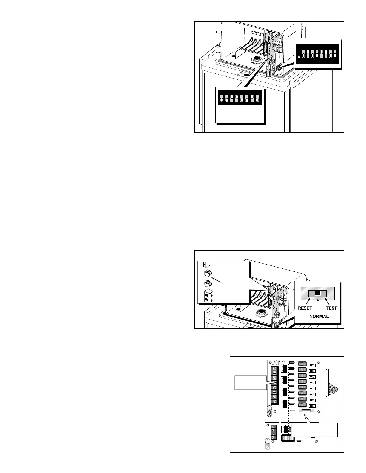
Service Components
Surge Devices – The surge protection modules utilize replaceable,
clip-mounted surge protection devices for each Valve Station and
Pump/Common terminal. The surge protection devices installed are quick
reaction, gas ionization type, commonly called “surge pills,” which momentarily
shunt high voltage directly to earth ground. Depending on the frequency and
severity of lighting strikes incurred, the surge pills can generally withstand
several high voltage surges before malfunction occurs. To ensure proper surge
pill condition, a periodic test schedule should be established and maintained.
Contact an authorized Toro distributor for service assistance.
5
 Loading...