Assembly
EN-6
1533
1
2
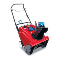
Figure 3
1. Chute
crank
2.
Chute crank gear
7. Secure upper and lower tubing and mounting
plate together with (2) #10–24 machine screws
and locknuts. Position screw heads on the
outside of the mounting plate.
Be car
eful not to
damage the internal electrical wiring when
inserting scr
ews. If hole is blocked, use a blunt
1/8” punch to carefully route electrical wiring
away from aligned holes.
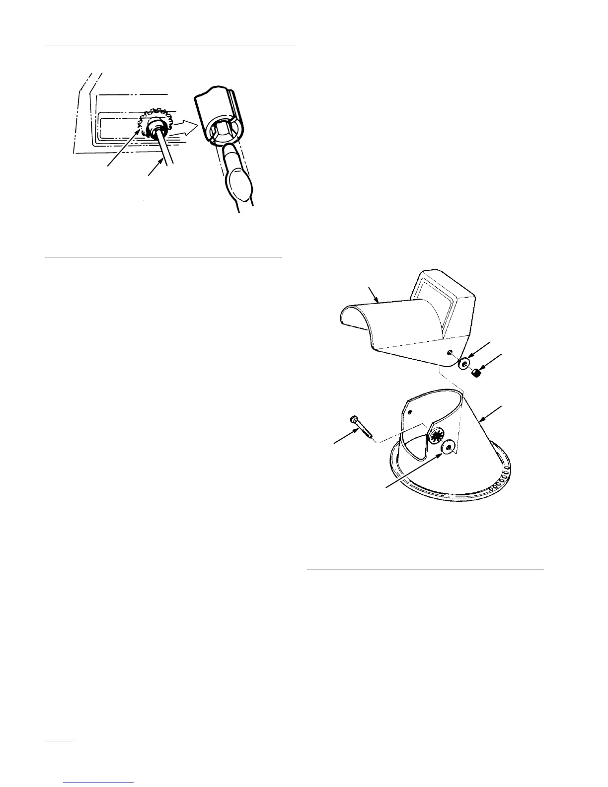
Install
Discharge Chute (Fig. 4)
1. Position deflector onto discharge chute, aligning
mounting holes. Insert a rubber washer between
deflector and discharge chute while maintaining
hole alignment.
2. Secure deflector to discharge chute with (2)
5/16–18 carriage bolts, metal washers, and
locknuts. Make sure the square shoulders on the
carriage bolts align with inside square on
discharge chute. Position metal washers to the
outside of deflector as shown in Figure 3. DO
NOT OVERTIGHTEN BOLTS.
1534
4
3
1
5
6
2
Figure 4
1. Chute
deflector
2. Chute
3.
Rubber washer
4.
Carriage bolt
5.
Metal washer
6. Locknut

 Loading...