Figure3
1.Cables
2.Securetheupperhandlewith4handlebolts,
4curvedwashers,and4locknutsfromtheloose
partsbag(
Figure4).
Figure4
2.InstallingtheTraction
ControlLinkage
Procedure
1.Removethehairpincotterandwasherfromthe
lowerendofthespeedcontrolrodandinsertthe
lowerendoftherodintothelowerlinkarmsothat
thebentendofthespeedcontrolrodfacesrearward
(Figure5).
Figure5
2.Securethelowerendofthespeedcontrolrodwith
thewasherandhairpincotterthatyoupreviously
removed.
3.Removethehairpincotterandtheouterwasher
fromthetrunnionontheupperendofthespeed
controlrod(Figure6).
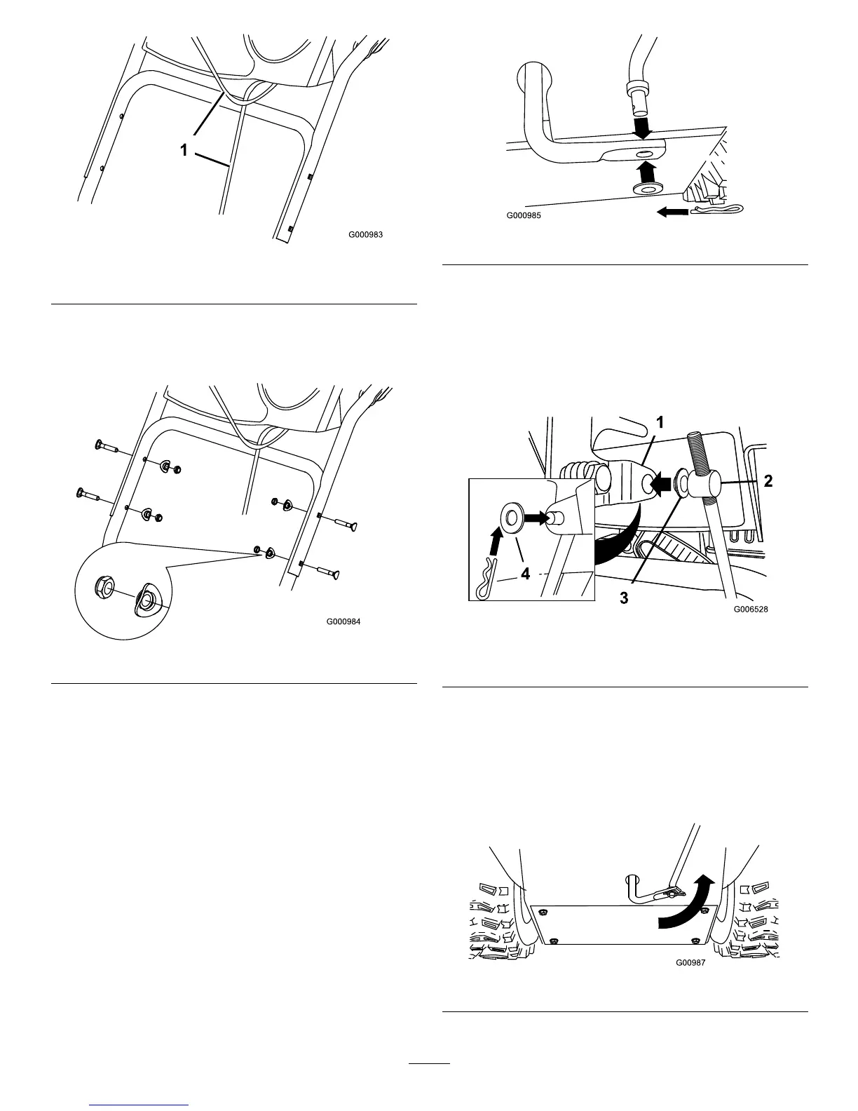
Figure6
1.Speedselectorlever
3.Innerwasher
2.Trunnion
4.Outerwasher
Note:Tomakeinstallationeasier,leavetheinner
washeronthetrunnion(Figure6).
4.ShiftthespeedselectorleverintoPositionR2.
5.Rotatethelowerlinkarmfullyupward
(counterclockwise)(
Figure7).
Figure7
8
 Loading...