18
Adjusting the Turf
Compensation Spring
Note: This adjustment is needed for Cutting Unit Models
03527 and 03528 only.
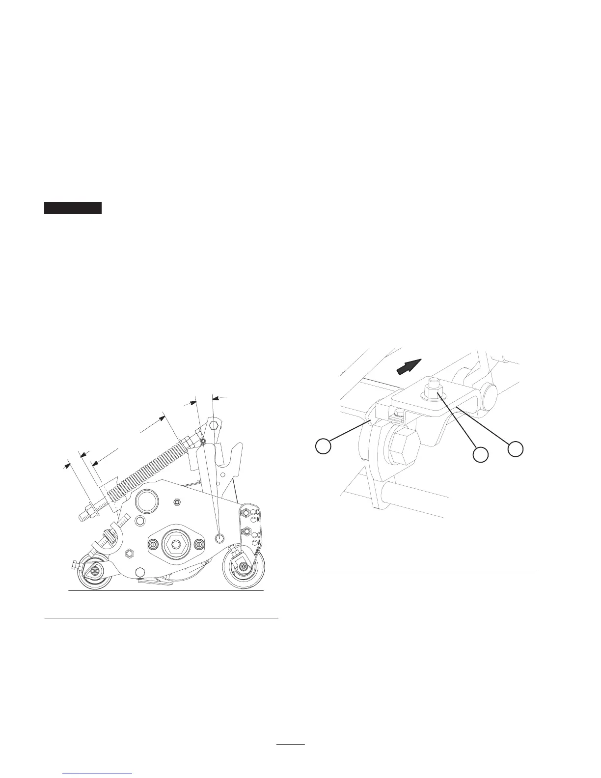
The turf compensation spring (Fig. 12), connecting carrier
frame to cutting unit, controls the amount of fore-aft
rotation available.
The Turf Compensation Spring also transfers weight from
the front to rear roller. (This helps to reduce a wave pattern
in the turf, also known as bobbing.)
Important Make spring adjustments with cutting unit
mounted to traction unit and lowered to shop floor.
1. Tighten locknut on rear of spring rod until the gap (C)
between rear of spring bracket and front of washer is
1.25 in. (32 mm) (Fig. 12).
2. Tighten hex nuts on front end of spring rod until the
compressed length (A) of spring is 6.25 in. (328 mm)
(Fig. 12).
Note: As compressed spring length (A) decreases, weight
transfer from front roller to rear roller increases and carrier
frame/cutting unit rotation angle (B) decreases.
Note: As gap (C) between spring bracket and washer
increases, carrier frame/cutting unit rotation angle (B)
increases.
“C”
“A”
“B”
Figure 12
Lifted Height of Outer Front
Cutting Units (Enable Position)
The turnaround height of the front outer cutting units (#4 &
#5) may be increased to provide additional ground
clearance on contoured fairways. Contact your distributor
for assistance.
Note: The RM CONFIG time delay should not be changed
from the original setting of 0 when using this method to
adjust turn around height.
To increase the turn around height of the front cutting units
proceed as follows:
• Position machine on a level surface, lower the cutting
units and stop the machine.
• Loosen the carriage bolt nut securing the lift arm switch
bracket to the No. 4 lift arm (left front) (Fig. 13).
• Move the lift switch bracket inward in the slot until the
desired position is attained.
• Set the distance between the lift arm switch and the flag
on the lift arm to approximately .062 inches.
• Tighten the carriage bolt nut.
1
2
3
Figure 13
1. Lift arm switch
2. Carriage bolt nut
3. Lift arm flag

 Loading...