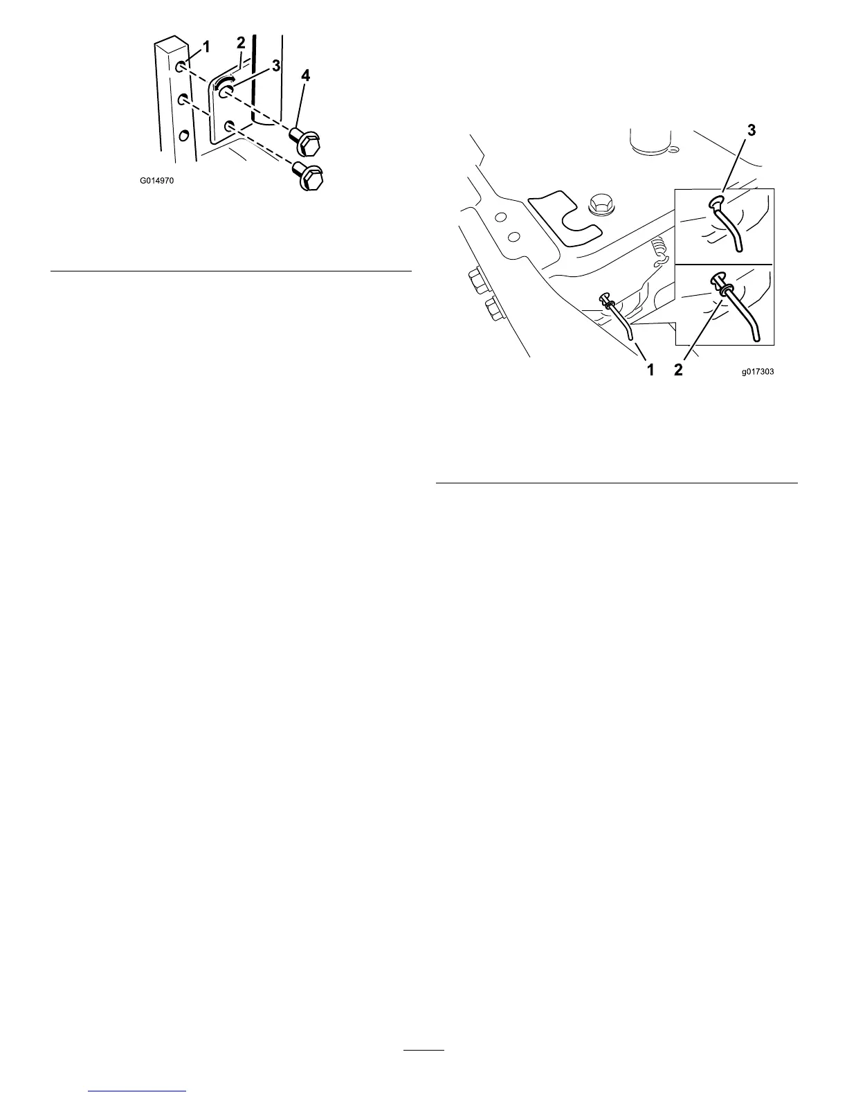
Figure23
1.Controlarmshaft3.Slotted,upperhole
2.Controllever
4.Bolt
3.Repeattheadjustmentfortheoppositecontrol
lever.
AdjustingtheTilt
Themotioncontrolleverscanbetiltedforeoraftfor
maximumoperatorcomfort.
1.Loosentheupperboltholdingthecontrolleverto
thecontrolarmshaft.
2.Loosenthelowerboltjustenoughtopivotthe
controlleverforeoraft(Figure23).Tightenboth
boltstosecurethecontrolinthenewposition.
3.Repeattheadjustmentfortheoppositecontrol
lever.
PushingtheMachinebyHand
Important:Alwayspushthemachinebyhand.
Nevertowthemachinebecausedamagemay
occur.
Thismachinehasanelectricbrakemechanismandto
pushthemachinetheignitionkeyneedstobeinthe
Runposition.Thebatteryneedstobechargedand
functioningfortheelectricbraketobedisengage.
ToPushtheMachine
1.Parkthemachineonalevelsurfaceanddisengage
thebladecontrolswitch.
2.Movethemotioncontrolleversoutwardtopark
position,stoptheengine,andwaitforallmoving
partstostopbeforeleavingtheoperatingposition.
3.Locatethebypassleversontheframeonbothsides
oftheengine.
4.Movethebypassleversforwardthroughthekey
holeanddowntolocktheminplaceasshownin
Figure24.Ensurethisisdoneforeachlever.
5.Movethemotioncontrolleversinwardtothe
neutralpositionandturntheignitionkeytotherun
position.Donotstartthemachine.
Themachineisnowabletobepushedbyhand.
Figure24
1.Bypassleverlocation
3.Leverpositionforpushing
themachine
2.Leverpositionfor
operatingthemachine
6.Whennished,ensurethekeyhasbeenreturned
totheStoppositiontoavoiddrainingthebattery
charge.
Ifthemachinefailstomovetheelectricbrake
maystillbeengaged.Ifnecessarytheelectric
brakecanbereleasedmanually.Refertothe
ReleasingtheElectricBrake(page35)procedurein
DriveMaintenance.
ToOperatetheMachine
Movethebypassleversrearwardthroughthekeyhole
anddowntolocktheminplaceasshowninFigure24.
Ensurethisisdoneforeachlever.
GrassDeector
Themowerhasahingedgrassdeectorthatdisperses
clippingstothesideanddowntowardtheturf.
23
 Loading...