Figure46
1.Opposingbladeedge,inpositionformeasuring
2.Levelsurface
3.Secondmeasureddistancebetweenbladeandsurface(B)
WARNING
Abladethatisbentordamagedcouldbreak
apartandcouldseriouslyinjureorkillyouor
bystanders.
•Alwaysreplacebentordamagedbladewith
anewblade.
•Neverleorcreatesharpnotchesinthe
edgesorsurfacesofblade.
A.IfthedifferencebetweenAandBisgreater
than1/8inch(3mm)replacethebladewitha
newblade.RefertoRemovingtheBladesand
InstallingtheBlades.
Note:Ifabentbladeisreplacedwithanewone
andthedimensionobtainedcontinuestoexceed
1/8inch(3mm),thebladespindlecouldbebent.
ContactanAuthorizedToroDealerforservice.
B.Ifthevarianceiswithinconstraints,movetothe
nextblade..
Repeatthisprocedureoneachblade.
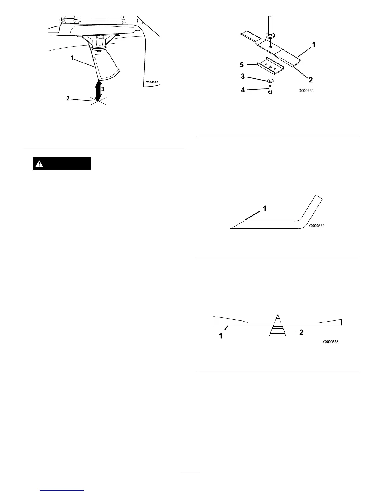
RemovingtheBlades
Thebladesmustbereplacedifasolidobjectishit,
ifthebladeisoutofbalance,orthebladeisbent.
Toensureoptimumperformanceandcontinued
safetyconformanceofthemachine,usegenuineToro
replacementblades.Replacementbladesmadebyother
manufacturersmayresultinnon-conformancewith
safetystandards.
Holdthebladeendusingaragorthickly-paddedglove.
Removethebladebolt,curvedwasher,bladestiffener,
andbladefromthespindleshaft(
Figure47).
Figure47
1.Sailareaofblade
4.Bladebolt
2.Blade
5.Bladestiffener
3.Curvedwasher
SharpeningtheBlades
1.Usealetosharpenthecuttingedgeatbothends
oftheblade(
Figure48).Maintaintheoriginalangle.
Thebladeretainsitsbalanceifthesameamountof
materialisremovedfrombothcuttingedges.
Figure48
1.Sharpenatoriginalangle
2.Checkthebalanceofthebladebyputtingitona
bladebalancer(
Figure49).Ifthebladestaysina
horizontalposition,thebladeisbalancedandcanbe
used.Ifthebladeisnotbalanced,lesomemetaloff
theendofthesailareaonly(Figure48).Repeatthis
procedureuntilthebladeisbalanced.
Figure49
1.Blade2.Balancer
InstallingtheBlades
1.Installthebladeontothespindleshaft(Figure47).
Important:Thecurvedpartoftheblademust
bepointingupwardtowardtheinsideofthe
mowertoensurepropercutting.
2.Installthebladestiffener,thecurvedwasher(cupped
sidetowardtheblade)andthebladebolt(Figure47).
3.Torquethebladeboltto35-65ft-lb(47-88N-m).
38
 Loading...