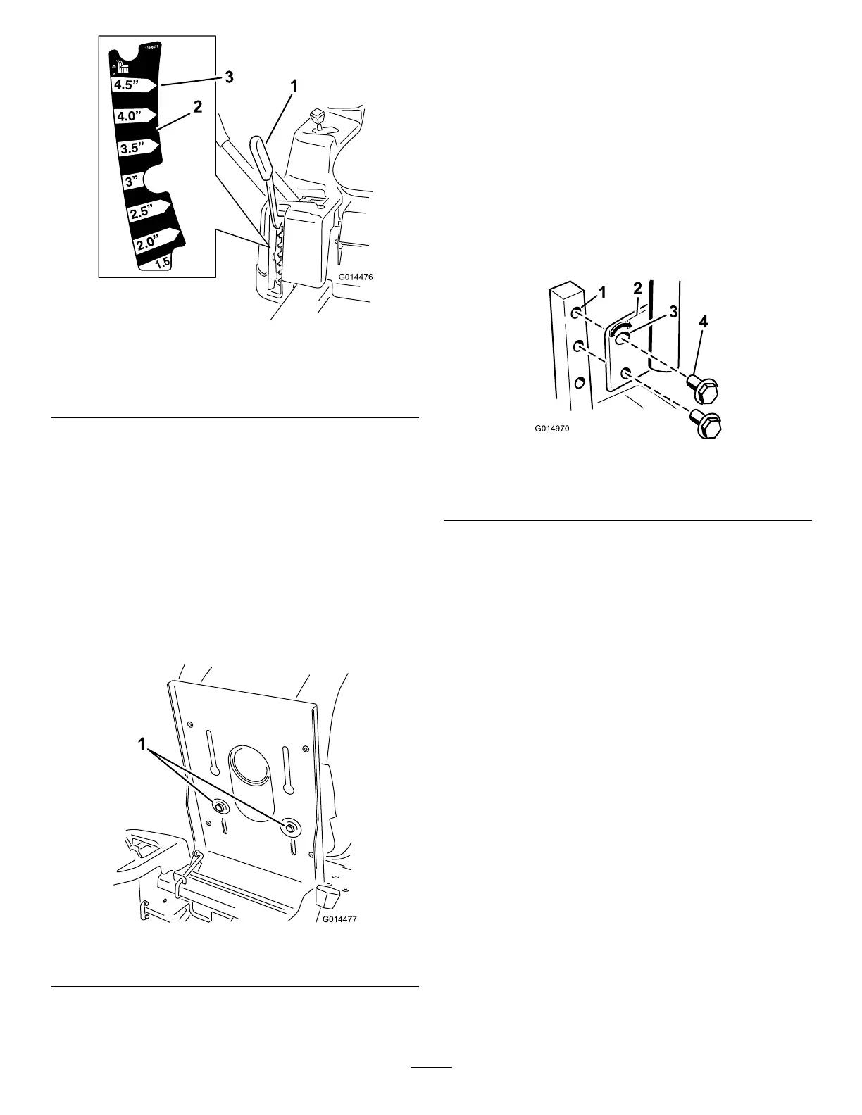
Figure20
1.Height-of-cutlever3.4.5inch(115mm),
Transportposition
2.Height-of-cutpositions
1.Pullupandinwardonthelevertomoveittothe
desiredcuttingposition.
2.Onceatthedesiredcuttingposition,slowlylower
theleveruntilitengagestheposition.
Thetransportpositionisthehighestheight-of-cut
positionorcuttingheight4.5inch[115mm](
Figure20).
PositioningtheSeat
1.Raisetheseatandloosentheadjustmentboltsjust
enoughthatseatcanmove(
Figure21).
Figure21
1.Adjustmentbolt
2.Movetheseattothedesiredpositionandtighten
thebolts.
AdjustingtheMotionControl
Levers
AdjustingtheHeight
Themotioncontrolleverscanbeadjustedhigheror
lowerformaximumoperatorcomfort.
1.Removethe2boltsholdingthecontrollevertothe
controlarmshaft(Figure22).
2.Movethecontrollevertothenextsetofholes.
Securetheleverwiththe2bolts(
Figure22).
Figure22
1.Controlarmshaft3.Slotted,upperhole
2.Controllever
4.Bolt
3.Repeattheadjustmentfortheoppositecontrol
lever.
AdjustingtheTilt
Themotioncontrolleverscanbetiltedforeoraftfor
maximumoperatorcomfort.
1.Loosentheupperboltholdingthecontrolleverto
thecontrolarmshaft.
2.Loosenthelowerboltjustenoughtopivotthe
controlleverforeoraft(
Figure22).Tightenboth
boltstosecurethecontrolinthenewposition.
3.Repeattheadjustmentfortheoppositecontrol
lever.
PushingtheMachinebyHand
Important:Alwayspushthemachinebyhand.
Nevertowthemachinebecausedamagemay
occur.
Thismachinehasanelectricbrakemechanismandto
pushthemachinetheignitionkeyneedstobeinthe
Runposition.Thebatteryneedstobechargedand
functioningfortheelectricbraketobedisengage.
20
 Loading...