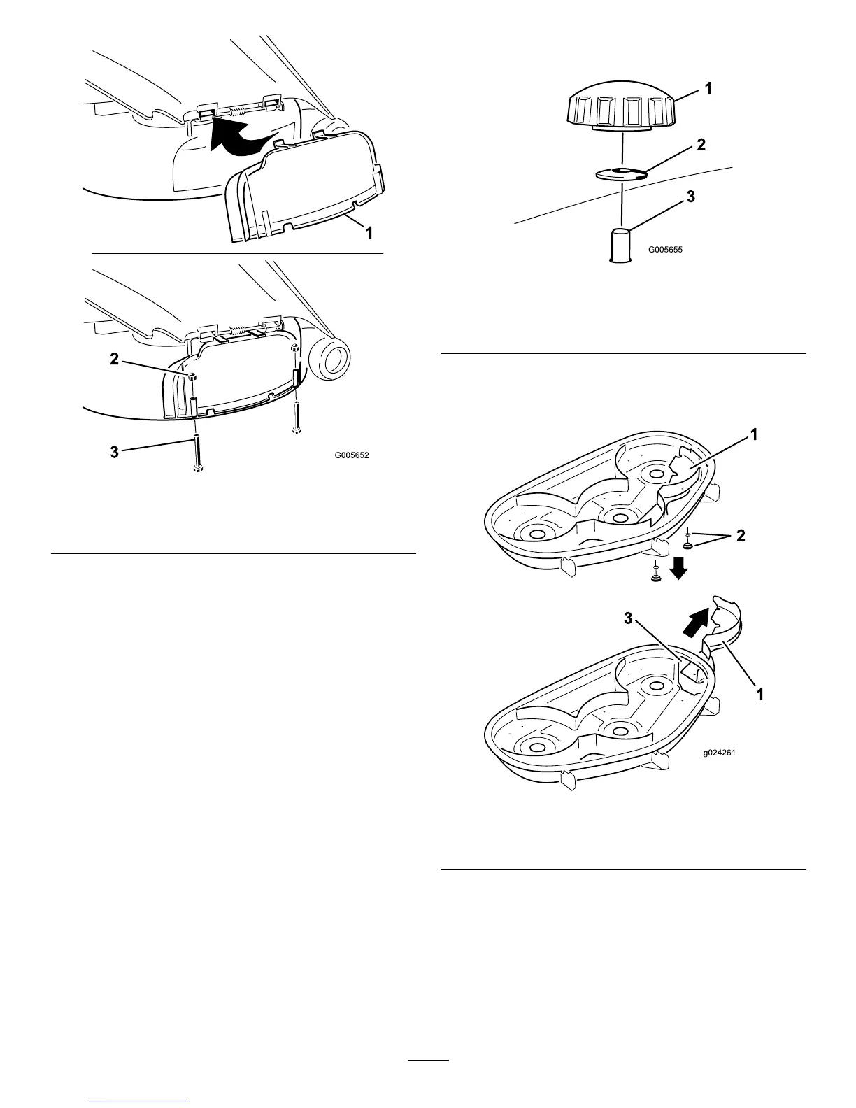
Figure22
1.Dischargecover
3.Bolt(1/4x2-1/2inches)
2.Capnut(1/4inch)
6.Securethedischargecovertothelowerlipofthe
mowerwith2bolts(1/4x2-1/2inches)and2capnuts
(1/4inch)asshowninFigure22.
Note:Donotovertightenthenuts;thiscoulddistort
thecoverandcausebladecontact.
ConvertingtoSideDischarge
(formodelswith127cm
(50-inch)decks)
Themowerdeckandmowerbladesshippedwiththismachine
weredesignedforoptimummulchingandsidedischarge
performance.
RemovingtheRightBafeforSide
Discharge
1.Parkthemachineonalevelsurfaceanddisengagethe
blade-controlswitch.
2.Ensuretheparkingbrakeisengaged,stoptheengine,
removethekey,andwaitforallmovingpartstostop
beforeleavingtheoperatingposition.
3.Removetherightmowerblade;refertoRemovingthe
Blades(page44).
4.Removethe2knobsandcurvedwashersthatsecure
therightbafetothemower(Figure23).
Figure23
1.Knob
3.Bafestudcomingthrough
themower
2.Curvedwasher
5.Removetherightbafeandlowerthegrassdeector
overthedischargeopeningasshowninFigure23and
Figure24.
Figure24
1.Rightbafe
3.Dischargeopening
2.Curvedwasherandknob
6.Installfastenersintotheholesinthetopofthemower
topreventyingdebris.
27

 Loading...