BleedingtheHydraulicSystem
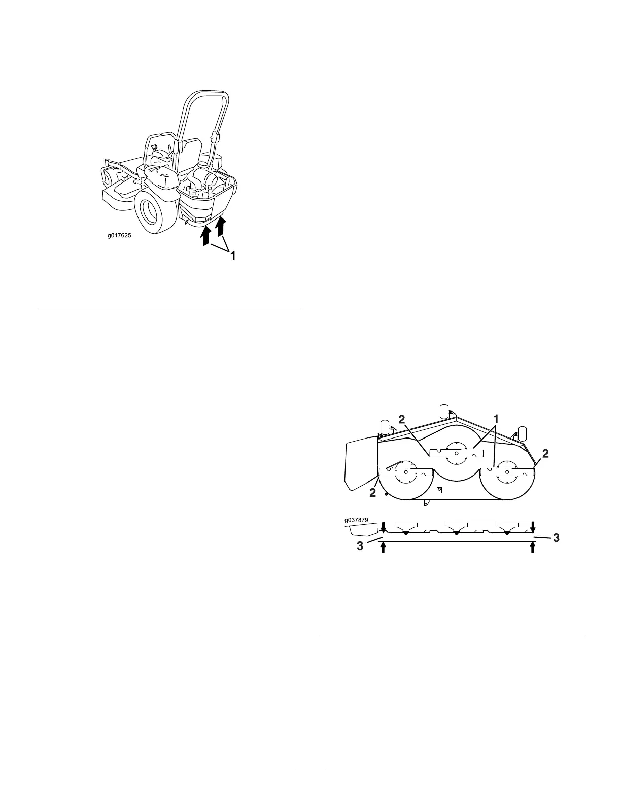
1.Raisetherearofmachineandsupportitwith
jackstands(orequivalentsupport)justhigh
enoughtoallowthedrivewheelstoturnfreely.
g017625
Figure100
1.Jackingpoints
2.Starttheengine,movethethrottlecontrolahead
tothe1/2throttleposition,anddisengagethe
parkingbrake.
A.Movethebypassleversintothepushingthe
machineposition.Withthebypassvalves
openandtheenginerunning,slowlymove
themotion-controlleversinbothforward
andreverse5or6times.
B.Movethebypassleversintotheoperating
themachineposition.
C.Withthebypassvalveclosedandthe
enginerunning,slowlymovethecontrol
leverinbothforwardandreversedirections
5to6times.
D.Shutofftheengineandchecktheoillevelin
theexpansionreservoir.Addthespecied
oiluntilitreachestheFULLCOLDlineonthe
expansionreservoir.
3.Repeatstep2untilalltheairiscompletely
purgedfromthesystem.
Note:Whenthetransaxleoperatesatnormal
noiselevels,movessmoothlyforward,and
reversesatnormalspeeds,itispurged.
4.Checktheoillevelintheexpansionreservoira
naltime.Addthespeciedoilasuntilitreaches
theFULLCOLDlineontheexpansionreservoir.
MowerDeck
Maintenance
LevelingtheMowerDeck
AdjustingtheSide-to-Side
LevelingandtheBladeSlope
1.Positionthemoweronaatsurface.
2.Disengagetheblade-controlswitch(PTO),move
themotion-controlleverstotheNEUTRAL-LOCK
position,andsettheparkingbrake.
3.Shutofftheengine,removethekey,andwait
forallmovingpartstostopbeforeleavingthe
operatingposition.
4.Checkthetirepressureinthedrivetires.Refer
toCheckingtheTirePressure(page60).
5.Positionthemowerdeckinthetransport-lock
position.
6.Carefullyrotatethebladesfromsidetoside.
7.Measurebetweenthebladetipandtheat
surface(Figure101).Ifbothmeasurementsare
notwithin5mm(3/16inch),adjusttheleveling;
continuewiththisprocedure.
g037879
Figure101
1.Bladessidetoside
3.Measurefromthetipofthe
bladetotheatsurface
here.
2.Bladetip
8.Checkthefront-to-rearbladelevel(Figure102).
Ensurethefrontbladetipislowerthantherear
bladetipasshownintheblockheightandrake
table.Ifadjustmentisneeded,continuewiththis
procedure.
72

 Loading...