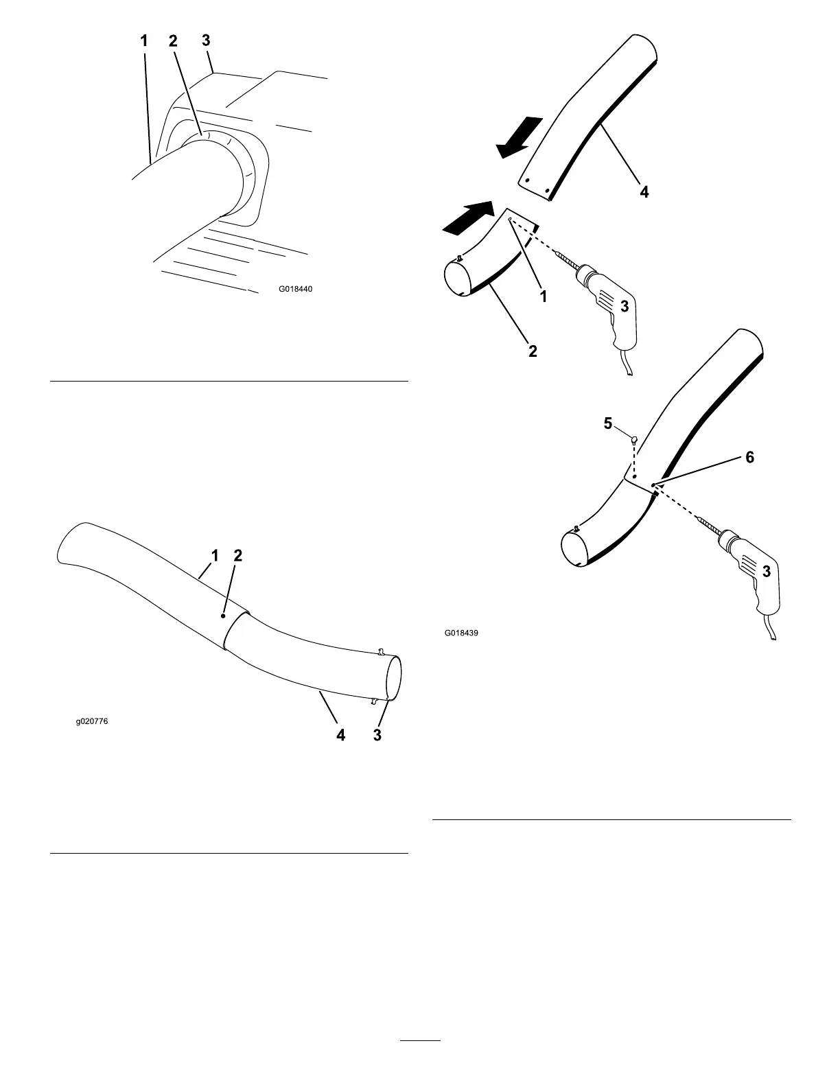
g018440
Figure31
1.Uppertube3.Baggerhood
2.Rubbersealprotrudingout
10.Aligntheuppertubeholestomatchthedimples
onthesurfaceofthelowertube.
Note:Ensurethatthesideproleappearsas
showninFigure32.
Note:Donotusetheopenholenearthe
moldedarrowheads.
g020776
Figure32
1.Uppertube
3.Notchatthebottomofthe
tubewheninstalled
2.Existinghole(bolt
removed)
4.Lowertube
11.Usingtheexistingholesintheuppertubeas
atemplate,drill2holes,6.5mm(1/4inch)
diameter,throughthedimplesonthelowertube
(Figure33).
g018439
Figure33
DrillingLowerDischargeTube
1.Dimples4.Uppertube
2.Lowertube
5.Installscrew(1/4x3/4
inch),washer(1/4inch),
andlocknut(1/4inch)
here.
3.Drill6.5mm(1/4inch)
diameterhole
6.Uppertube—existing
holes
12.Removetheupperandlowertubesfromthe
machine.
13.Slidethetubestogetherandaligntheholes.
14.Installthewashers(1/4inch)ontothebolts
(Figure33).
15.Usingahexkeytool,installthescrews(1/4x
3/4inch)andwashers(1/4inch)fromtheinside
ofthelowertubeandthroughtheexistingholes
intheuppertube(Figure33).
22
 Loading...