EasyManua.ls Logo

Toshiba 20AF45 User Manual

Toshiba 20AF45
50 pages
To Next Page IconTo Next Page
To Previous Page IconTo Previous Page
Page #26 background imageLoading...
Page #26 background image
CME017A
CCE011A
RISK OF FIRE
- REPLACE AS MARKED .
SERVICE
FOR
INFORMATION
ABOUT
CRITICAL
COMPONENTS SEE INSIDE
BACK
COVER.
CAUTION
,
ATTENTION
INFORMATION
POUR
SERVICE
DES
PIECE
CRITIQUE
VOIR AU VERSO.,
20AF45/20AF45C
Q514
D524
R543
D507
R544
R545
C503_1
C502_1
Q402
D411
W004
W801
B501
T501
FH502
F501
FH501
CP501
CP502
D502
D503
D501
R500
D523
RY501
R520
R540
R501
L501
D516
R503
C403
C504
D505
D520
Q504
B504
C520
C501
D511
W002
W010
R430
C408
R429
R433
R416
R413
R420
CP401
R427
TP003
R443
R437
R441
R414
R428
IC401
R432
R439
C426
D404
D415
D410
D403
W019
R
527
R506
D528
Q507
R553
R554
VR502
CP101
D402
HS402
C425_1
TP004
CP801A
FB401
C418
C420_1
R406
R421
IC504
C409
C539_1
C430
C407
C406
R502
D506
Q502
R542
C509
HS501
R547
D525
W825
D504
Q503
R507
R536
R535
R505
W806
D517
D513
R410_1
T401_1
J704
J702
J1001 J705
J706
J707
W179
W177
W178
CP1001
C904
C905
C907
C916
C910
C914
C903
W174
W175
L301
C302
C306
R301
C305
C308
C314
C316
C333
C304
SW105
R120
OS101
C108
D109
SW102
R515
W053
W822
W120
C122
C110
R139
R140
SW103
SW104
SW101
R102
W128
R119
D105
C109
D104
W055
D106
R133
W056
W093
W116
C317
C319
D608
W176
R002
R001
W027
W098
R539
CP802A
W102
R124
W094
W105
D709
W133
IC1001
HS1001
W858
W137
W138
L1503
W018
C001_1
L1501
C1532
W146
C642
C610
D602
D601
R603
X602
C630
C622
Q607
W108
C621
C618
C611
Q606
Q604
Q602
C605
R649
C603
R616
W151
W152
Q601
Q611
C602
R601
C606
R132
W113
R626
R623
W139
C615
C413_1
D509
R508
TP006
TP005
D604
D514
W043
C919
D407
C114
VR401_1
R422
R418
W089
R146
D510
W812
C733
D701
D703
D702
R602
C609
R510
W013
R303
R304
D706
D704
W123
C139
J701
R546
C645
C629
D607
D605
D606
W050
TH501_2
C402
C415_1
C417_1
C508_1
C512
C513_1
C
5
1
9
_
1
C524
D512
W821
W065
C427_1
C521_1
D508
R524
Q505
Q512
R541_1
C507
X101_1
C638
D405
W863
TU001
R436
W070
W068
W187
W090
D001
W081
W109
W104
W112
W154
W859
W172
W049
W052
R118
R130
W028
W114
W045
W025
W103
L901
W180
W048
W046
W110
C801
R824
CP802B
R805
W802
R802
R
8
03
R
80
7
CP803
CP806
D803
D801
D802
Q803
Q801
Q802
J8
01
_
1
D811
D810
D812
R806
C1513_1
C1514
B1502
R1516
R1507
R1515
R1503
C1512
W066
W091
W129
W167
W169
W092
R617
R612
W106
W107
C1515
W121
W118
W125
W100
R302
W170
W165
W160
W003
W001
W009
W079
C527
W145
W142
W057
W115
W143
W831
L402_1
CP507
CP508
C535_1
R434
C505_1
C506_1
C641
R1012
R1013
W007
L401
C410
W850
W813
C614
C725
C722
C517_1
W054
C802
Q806
Q804
Q805
L1504
R1014
C1012
C1011
R1015
W014
W017
W015
W016
W162
R1010
C1009
C1005
W005
C1006
R1002
W008
W069
W072
R1001
W059
W134
W135
C619
W075
W073
W077
W076
W185
W006
R1016
R407
W022
W024
R452_1
D414
R426
R537
W030
W041
W040
W032
W035
W033
R804
W039
D406
W044
W086
W067
W037
C1501
R453
C1503
R1511
W020
L1507
W111
W012
W021
W087
W862
W144
W164
W011
W074
W833
W832
C113
R402
C1521
W140
W058
W147
W071
W097
W805
W096
W095
W078
W820
W819
W844
W837
W815
W861
W817
W829
W830
W848
W857
W865
C1504_1
W853
W871
C633
R438_1
W155
C514_1
S801X
S801Y
R518
S802X
S802Y
Q405
C608_2
S803Y
S803X
CP801B
PRINTED CIRCUIT BOARDS
MAIN/CRT (INSERTED PARTS)
SOLDER SIDE
F-1 F-2
TP024
TP022
Question and Answer IconNeed help?

Do you have a question about the Toshiba 20AF45 and is the answer not in the manual?
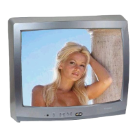
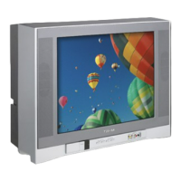
Toshiba 20AF45 Specifications

General IconGeneral
Screen Size20 inches
Display TypeCRT
Resolution480i
Aspect Ratio4:3
InputsComposite

Summary

Servicing Notices on Checking

Keep the Notices

Describes labels and seals indicating special attention areas during servicing.

Avoid Electric Shock

Cautionary note regarding high voltage parts inside the equipment.

Use Designated Parts

Emphasizes using specific parts with safety characters for replacements.

Original Position for Parts and Wires

Instructions to return parts and wires to their original positions after assembly.

Cathode-Ray Tube Handling

Cautionary advice for handling the cathode-ray tube during servicing.

X-Ray Safety Precautions

Notes on avoiding X-ray emission by using designated parts.

Post-Servicing Safety Check

Procedure for performing a safety check after completing repairs.

How to Order Parts

Important Maintenance Note

About Lead Free Solder (PbF)

PbF PCB Distinction

Identifies Printed Circuit Boards (PCBs) manufactured using lead-free solder.

Lead Free Solder Handling Caution

Cautions regarding higher melting points and handling of lead-free solder.

Solder Composition Recommendations

Recommendation for lead-free solder composition.

General Specifications: TV System and Tuning

CRT, Speaker, and Broadcast System Details

Specifications for CRT, speaker, color system, and broadcast system.

Tuner and Frequency Specifications

Details on tuner system, intermediate frequency, and channel coverage.

General Specifications: Power, Regulation, and Environment

Power Source, Consumption, and Protectors

Information on power source, consumption, and protective circuits.

Safety, Radiation, Temperature, and Humidity

Safety compliance, radiation standards, and operating environment specs.

General Specifications: On-Screen Display and Clock Functions

OSD Menu Options and Language

Details on on-screen display menu types, options, and language settings.

Clock and Timer Settings

Specifications for sleep timer, on/off timer, and wake-up timer functions.

General Specifications: Remote Control

Remote Control Unit Features

Details on the remote control unit, including keys and functions.

General Specifications: Unit Features and Accessories

Product Features List

List of various features supported by the television unit.

Included Accessories List

List of accessories provided with the television.

General Specifications: Interface and Physical Data

Input/Output Interfaces and Connectors

Details on front and rear input/output interfaces and terminals.

Physical Dimensions, Weight, and Packaging

Specifications for unit dimensions, weight, carton, and drop test.

Cabinet Material and Environmental Specifications

Information on cabinet material and environmental requirements.

Disassembly Instructions

Anode Cap Removal Procedure

Step-by-step guide for safely removing the anode cap.

Flat Package IC Removal and Installation

Procedure for removing and installing flat package integrated circuits.

Service Mode List

Confirming Power On Hours

Instructions on how to check the total power on hours of the unit.

EEPROM (Memory) IC Replacement

Procedure for replacing the EEPROM IC and setting data.

Electrical Adjustments: Overview and Basic Settings

Adjustment Procedure and Tools

Overview of electrical adjustments and required measurement tools.

Basic Adjustments: Voltage, Cut Off, White Balance

Procedures for constant voltage, cut off, and white balance adjustments.

Focus Adjustment

Procedure for adjusting the picture focus.

Electrical Adjustments: Picture and Timing Settings

Vertical Position and Size Adjustment

Adjusting vertical position, size, and over scan.

Vertical Linearity and Level Adjustment

Adjusting vertical linearity and signal level.

Horizontal Phase and Contrast Max Settings

Adjusting horizontal phase and maximum contrast.

Separation Adjustments

Procedures for adjusting audio separation (SEP 1 and SEP 2).

Electrical Adjustments: Display and Color Settings

OSD Position Adjustment

Adjusting the position of the on-screen display elements.

Brightness and Color Center Adjustment

Adjusting brightness center and color center for picture quality.

Tint Adjustment

Procedure for adjusting the picture tint for accurate color.

Electrical Adjustments: Fixed Value Confirmation

Verifying Adjustment Item Values

Checking fixed values for various adjustment items (RF, AV, CS).

Purity and Convergence Adjustments

Static Convergence (Rough) and Purity

Initial steps for static convergence and purity adjustments.

Static and Dynamic Convergence Fine Tuning

Fine-tuning static and dynamic convergence for precise picture alignment.

Electrical Adjustment Parts Location Guide

Wiring Connections for Adjustments

Guide illustrating wiring connections for electrical adjustments.

Block Diagram

Main PCB Signal Flow

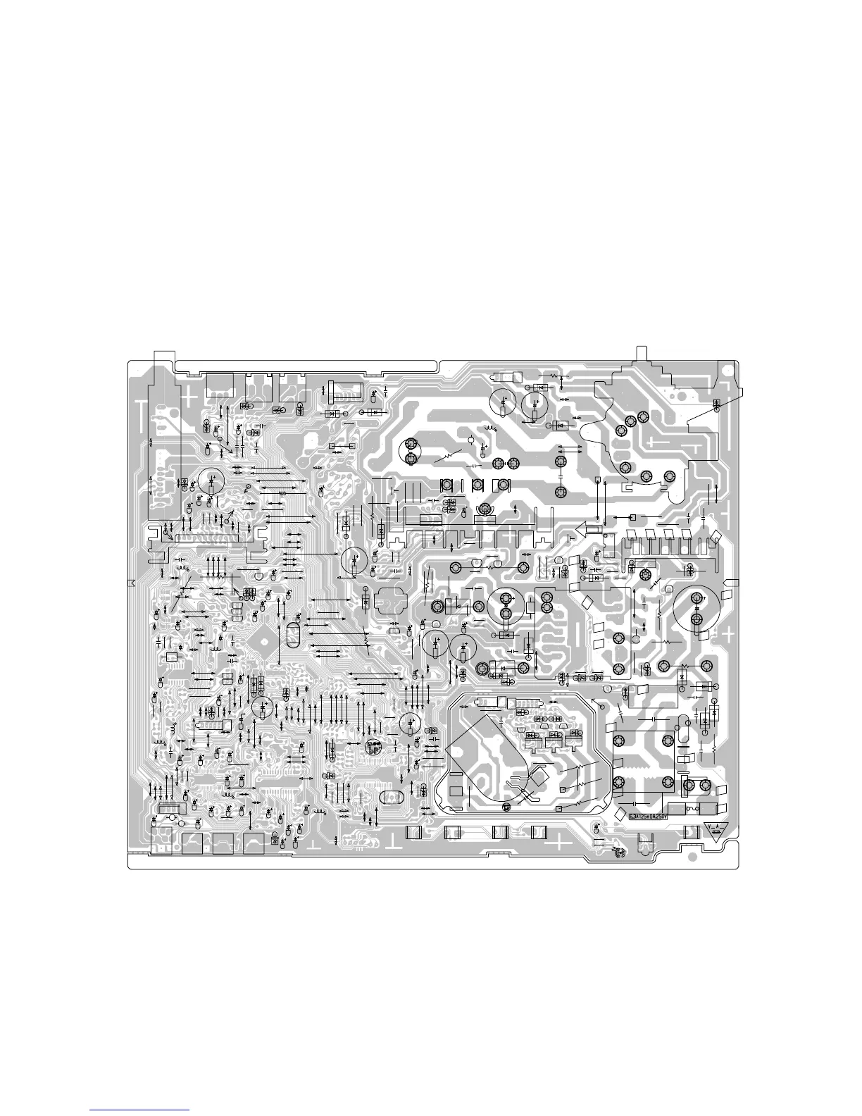
Diagram showing signal paths and connections on the Main PCB.

Printed Circuit Boards: Main/CRT

Component Layout - Solder Side

Visual guide to component placement on the Main/CRT PCB solder side.

Printed Circuit Boards: Main/CRT

Component Layout - Chip Parts

Visual guide to chip component placement on the Main/CRT PCB.

Schematic Diagrams: Micon

Micon IC and Associated Circuitry

Schematic diagram for the Micon Integrated Circuit and its connections.

Schematic Diagrams: Chroma

Chroma IC and Associated Circuitry

Schematic diagram for the Chroma Integrated Circuit and its connections.

Schematic Diagrams: Deflection

Deflection IC and Associated Circuitry

Schematic diagram for the Deflection Integrated Circuit and its connections.

Schematic Diagrams: Power

Power Supply Circuitry

Schematic diagram of the power supply circuit.

Schematic Diagrams: Sound

Sound ICs and Associated Circuitry

Schematic diagram for the Sound ICs and associated circuitry.

Schematic Diagrams: Tuner/Stereo

Tuner and Stereo ICs and Circuitry

Schematic diagram for the Tuner/Stereo ICs and associated circuitry.

Schematic Diagrams: Comb/Filter/AV

Comb Filter IC and Associated Circuitry

Schematic diagram for the Comb Filter IC and associated circuitry.

Schematic Diagrams: CRT

CRT PCB Components and Circuitry

Schematic diagram for the CRT PCB, showing components and connections.

Waveforms: Micon and Chroma

Micon Signal Waveforms

Illustrations of typical waveforms measured at Micon points.

Chroma Signal Waveforms

Illustrations of typical waveforms measured at Chroma points.

Waveforms: Deflection, Sound, and Video

Deflection, Sound, and Comb/Filter/AV Waveforms

Illustrations of waveforms for Deflection, Sound, and Comb/Filter/AV signals.

CRT Signal Waveforms

Illustrations of typical waveforms measured at CRT signal points.

Mechanical Exploded View

Chassis Assembly Exploded Diagram

Exploded view showing the assembly of the television chassis.

Mechanical Exploded View: Packing Diagram

Packaging Components Exploded Diagram

Exploded view illustrating the packaging components.

Mechanical Replacement Parts List

Cabinet and Structural Parts

List of replacement parts for the cabinet and structural components.

Hardware, Holders, and Felt Sheets

List of replacement hardware, holders, and felt sheets.

Mechanical Replacement Parts List

Packaging, Labels, and Instruction Materials

List of replacement parts for packaging, labels, and instructions.

Various Hardware Components

List of various screws and other hardware replacement parts.

Electrical Replacement Parts List: Resistors, Capacitors, and Diodes

Resistors List

List of replacement resistors with their values and specifications.

Capacitors List

List of replacement capacitors with their values and specifications.

Diodes List

List of replacement diodes with their types and specifications.

Electrical Replacement Parts List: ICs and Transistors

ICs List

List of replacement Integrated Circuits (ICs) and their specifications.

Transistors List

List of replacement transistors and their specifications.

Electrical Replacement Parts List: Coils, Transformers, and Jacks

Coils, Transformers, and Jacks List

List of replacement coils, transformers, and audio/video jacks.

Switches, Variable Resistors, and PC Boards

List of replacement switches, variable resistors, and PC boards.

Miscellaneous Components List

List of miscellaneous replacement parts like fuses, batteries, and speakers.

Related product manuals