1-11-1 E9TK3TR
TROUBLESHOOTING
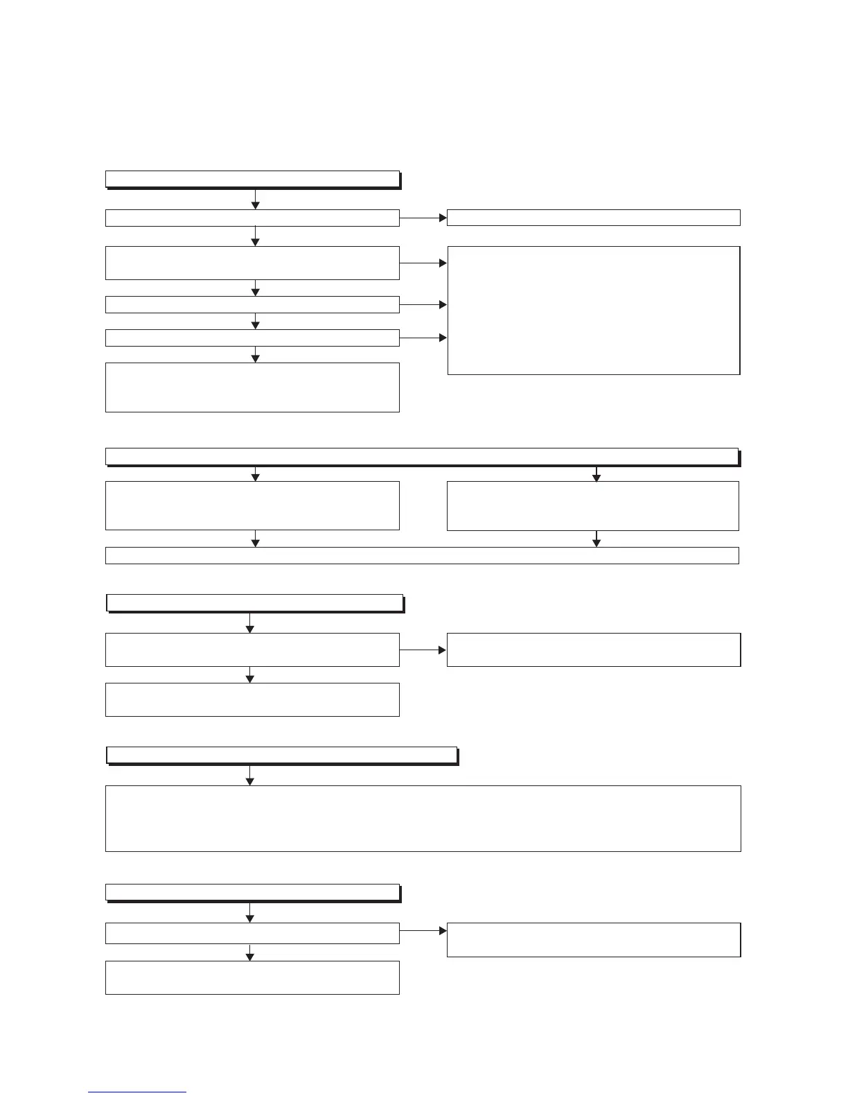
1 Power Supply Section
NOTE: BOARD MEANS PRINTED CIRCUIT BOARD.
Check for load circuit short-circuiting or leak, and
replace P1(AV ASSEMBLY) if defective.
FLOW CHART NO.1
The power cannot be turned on.
Is the fuse normal?
Is normal state restored when once unplugged power
cord is plugged again after several seconds.
Is the AL+5V line voltage normal?
Check each rectifying circuit of secondary circuit and
replace P1(AV ASSEMBLY) or P4(PW/SW ASSEMBLY)
if defective.
See FLOW CHART No.2 <The fuse blows out.>
Check for lead or short-circuiting of primary circuit
component and replace P4(PW/SW ASSEMBLY)
if defective.
SYS+5V (IC1051, IC1052, IC1151, D1051, D1052,
D1053, D1054, D1057, D1058, D1152, R1054, T1051,
RL1001)
AL+5V (Q1001, Q1003, T1001, D1001, D1002, D1003,
D1004, D1011, D1102, D1140, R1003)
Ye s
Ye s
Ye s
No
No
No
Is the SYS+5V line voltage normal?
Ye s
No
FLOW CHART NO.2
The fuse blows out.
After servicing, replace the fuse.
Check the presence that the primary component is
leaking or shorted and replace P4(PW/SW ASSEMBLY)
if defective.
Check the presence that the rectifying diode or circuit
is shorted in each rectifying circuit of secondary side
and replace P4(PW/SW ASSEMBLY) if defective.
FLOW CHART NO.3
When the output voltage fluctuates.
No
Ye s
Does the secondary side photo coupler circuit operate
normally?
Check the circuit and replace P4(PW/SW ASSEMBLY)
if defective. (IC1001, D1025, D1022, D1023)
Check the circuit and replace P4(PW/SW ASSEMBLY)
if defective. (IC1001, IC1101, D1102)
FLOW CHART NO.4
When buzz sound can be heard in the vicinity of power circuit.
Check if there is short circuit on the rectifying diode and the circuit in each rectifying circuit of secondary side, and
replace P1(AV ASSEMBLY) or
P4(PW/SW ASSEMBLY)
if defective. (D013, D014, D016, D018, D019, D1031, D1032,
D1033, D1034, D1101, D1103, IC1103, IC1104, Q1100, Q1106, Q1108, Q1112, Q1119, Q1508, Q1511, Q1513, Q1516,
Q1517, Q1520, Q1521, Q1527)
No
Ye s
FLOW CHART NO.5
-FL is not outputted.
Is the supply voltage of -36V fed to the anode of D018?
Check D018, D020 and their periphery, and replace
P4(PW/SW ASSEMBLY) if defective.
 Loading...