– 16 –
31-EN 32-EN
EN
FR
■ Pipe insulation
• Apply pipe insulation separately to liquid, gas, and balance lines.
• All insulation should have a minimum temperature rating of 248°F (120°C).
■ Finishing pipe work
1. After all piping and insulation is complete. Fill the remaining gap at the piping panel with silicon sealer.
2. If the piping was routed down or to the side, the remaining gap should be filled with silicon sealer.
Piping/wiring panel
Pipe routed to front
Pipe routed down
Fill space with silicon sealer
Pipe routed to side
When not using the piping cover
8 Electric wiring
WARNING
The equipment shall be installed in compliance with NEC and local codes.
CAUTION
• Do not connect high voltage power wires to the control terminal blocks (U1, U2, U3, U4, U5, U6);
• All fi eld wiring insulation rating must comply with NEC and local codes.
• All wiring must be strained relieved as specifi ed by NEC and local codes.
• Refrigerant piping and control wiring should use the same routing.
• Do not energize the indoor units until leak check and vacuuming are completed.
• For indoor unit power and control wiring see indoor unit installation instructions.
NOTE
• Use copper supply wires.
• Use UL wires rated 600V for the system interconnection wires.
• Use UL wires rated 300V for remote control wires.
1. All service valves on the outdoor units should remain fully closed.
2. R410A refrigerant should be added (in liquid state) at the liquid line service port on the header unit.
3. If the calculated amount of refrigerant can added to the system, the charging process is finished.
4. If the total calculated amount of refrigerant cannot be added to the system, close the valve on the refrigerant
bottle, move the charging hose from the liquid line service port to the suction line service port.
5. Open the suction and liquid service valves on the header unit and start the system in cooling mode.
6. Slowly open the valve on the refrigerant bottle and carefully release liquid refrigerant into the suction service
port.
7. If the total calculated charge amount is added completely to the system, the charging process is finished.
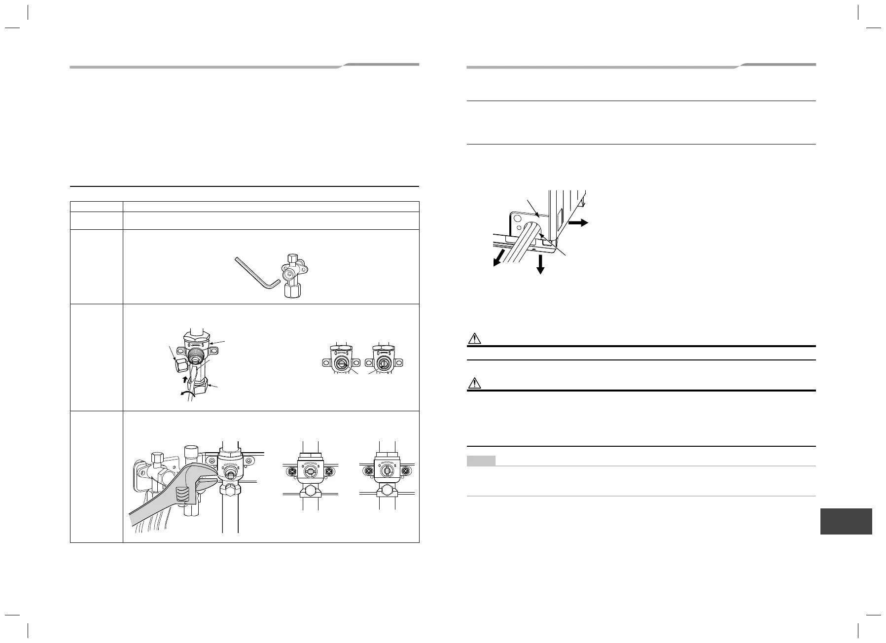
■ Full opening of the valve
Open the valves of the outdoor unit fully.
MAP072
Balance pipe
Packed valve
Using a 4 mm-hexagonal wrench, fully open the valve shaft.
Liquid side
Ø1/2" packed valve
Using a 4 mm-hexagonal wrench, fully open the valve shaft.
Discharge gas
side
Ball valve
Using a flathead screwdriver, turn it counterclockwise by 90° until it hits the stopper. (Full open)
(1)
(2)
Valve unit
Flare nut
Service port
Using flathead screwdriver, turn
it counterclockwise by 90° until
it hits the stopper. (Full open)
Position of screwdriver slot
Slot
Fully closed Fully opened
* When opened fully, do not apply excessive
torque after the screwdriver hits the stopper;
otherwise a problem may be caused on the
valve. (3.7 ft•lbs (5 N•m) or less)
Suction gas side
Ball valve
Using a wrench, turn the valve shaft counterclockwise by 90° until it hits the stopper. (Full open)
Fully closed Fully opened
1122001201_EN FR.indd 161122001201_EN FR.indd 16 9/2/16 1:30 PM9/2/16 1:30 PM
 Loading...