Piping and Drain Hose Installation
* Since dewing results in a machine trouble, make sure to insulate both
connecting pipes. (Use polyethylene foam as insulating material.)
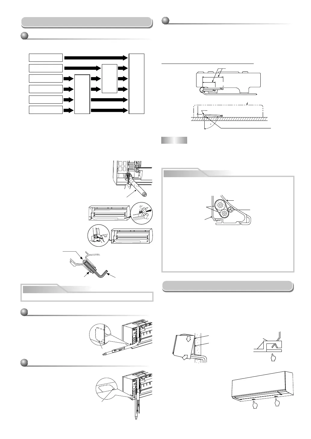
Piping and drain hose forming
1. Die-cutting back body slit
Cut out the slit on the left or right side of the back body for the left or right
connection and the slit on the bottom left or right side of the back body
for the bottom left or right connection with a pair of nippers.
Rear right
Rear left
Bottom left
Left
Bottom right
Right
Die-cutting
back body slit
Changing
drain hose
Piping preparation
2. Changing drain hose
For leftward connection, bottom-leftward connection and rear leftward
connection’s piping, it is necessary to change the drain hose and drain cap.
How to remove the drain cap
Clip the drain cap by needle-nose
pliers and pull out.
How to remove the drain hose
The drain hose can be removed by removing the
screw securing the drain hose and then pulling out
the drain hose.
When removing the drain hose, be careful of any
sharp edges of steel plate. The edges can injuries.
To install the drain hose, insert the drain hose
fi rmly until the connection part contacts with heat
insulator, and then secure it with original screw.
How to fi x the drain cap
1) Insert hexagon wrench (4 mm)
in a center head.
2) Firmly insert the drain cap.
Firmly insert the drain hose and drain cap; otherwise, water may leak.
CAUTION
Drain hose
Do not apply lubricating oil
(refrigerant machine oil)
when inserting the drain
cap. Application causes
deterioration and drain
leakage of the plug.
Insert a hexagon wrench
(4 mm).
No gap
NOTE
If the pipe is bent incorrectly, the indoor unit may unstably be set on the wall.
After passing the connecting pipe through the pipe hole, connect the
connecting pipes to the auxiliary pipes and wrap the facing tape around
them.
CAUTION
Bind the auxiliary pipes (two) and connecting cable with facing tape
tightly. In case of leftward piping and rear-leftward piping, bind the
auxiliary pipes (two) only with facing tape.
Indoor unit
Connecting cable
Auxiliary pipes
Installation plate
Carefully arrange pipes so that any pipe does not stick out of the rear
plate of the indoor unit.
Carefully connect the auxiliary pipes and connecting pipes to one
another and cut off the insulating tape wound on the connecting pipe
to avoid double-taping at the joint; moreover, seal the joint with the
vinyl tape, etc.
Since dewing results in a machine trouble, make sure to insulate both
connecting pipes. (Use polyethylene foam as insulating material.)
When bending a pipe, carefully do it, not to crush it.
Left-hand connection with piping
Bend the connecting pipe so that it is laid within 43 mm above the wall
surface. If the connecting pipe is laid exceeding 43 mm above the wall
surface, the indoor unit may unstably be set on the wall.
When bending the connecting pipe, make sure to use a spring bender so
as not to crush the pipe.
Bend the connecting pipe within a radius of 30 mm.
To connect the pipe after installation of the unit (fi gure)
80
260 mm
210 mm
43 mm
Liquid side
Gas side
(To the forefront of fl are)
Outward form of indoor unit
R 30 mm (Use polisin (polyethylene)
core or the like for bending pipe.)
Use the handle of screwdriver, etc.
In case of bottom right or bottom left piping
After scribing slits of the back body
with a knife or a making-off pin, cut
them with a pair of nippers or an
equivalent tool.
Slit
In case of right or left piping
After scribing slits of the back body
with a knife or a making-off pin, cut
them with a pair of nippers or an
equivalent tool.
Slit
1
2
1
Hook here.
Installation plate
Hook
Press
(unhook)
Push
Push
Indoor Unit Fixing
For detaching the indoor unit
from the installation plate, pull
the indoor unit toward you while
pushing its bottom up at the
specifi ed parts.
1. Pass the pipe through the hole in the wall and hook the indoor unit on the
installation plate at the upper hook.
2. Swing the indoor unit to right and left to confi rm that it is fi rmly hooked up
on the installation plate.
3. While pressing the indoor unit onto the wall, hook it at the lower part on
the installation plate. Pull the indoor unit toward you to confi rm that it is
fi rmly hooked up on the installation plate.
8
 Loading...