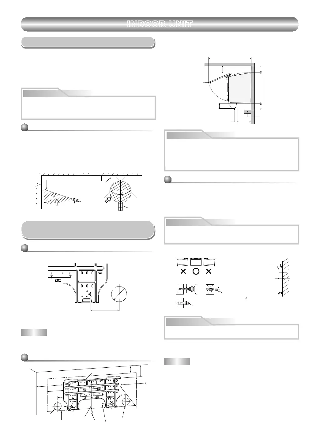
If have curtain rails, window cornice or other objects, allow space from
the indoor unit should be 65 mm or more.
,IDOORZVSDFHLVOHVVWKDQPPWKLVFDQDIIHFWWKHRSHQLQJDQG
FORVLQJRIWKHDLULQOHWJULOOHDQGWKHKRUL]RQWDOORXYHU
+RZHYHUWKHUHVKRXOGEHQRREMHFWVLQWKHDLURXWOHWSRVLWLRQ
It will block the air flow direction and drop performance.
CAUTION
Ø4 mm x 25
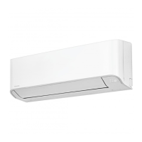
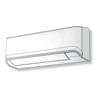
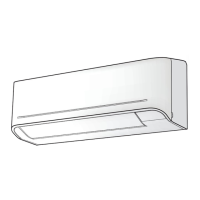
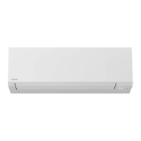
INDOOR UNIT
Installation Place
'LUHFWVXQOLJKWWRWKHLQGRRUXQLW’s wireless receiver should be avoided.
The microprocessor in the indoor unit should not be too close to RF
noise sources.
(For details, see the owner’s manual.)
Remote control
A place where there are no obstacles such as a curtain that may block the
VLJQDOIURPWKHLQGRRUXQLW
'RQRWLQVWDOOWKHUHPRWHFRQWUROLQDSODFHH[SRVHGWRGLUHFWVXQOLJKWRU
FORVHWRDKHDWLQJVRXUFHVXFKDVDVWRYH
Keep the remote control at least 1 m apart from the nearest TV set or
VWHUHRHTXLSPHQW7KLVLVQHFHVVDU\WRSUHYHQWLPDJHGLVWXUEDQFHVRU
noise interference.)
The location of the remote control should be determined as shown below.
Cutting a Hole and Mounting
Installation Plate
NOTE
When GULOOLQJ a wall that contains a metal lath, wire lath or metal plate, be
sure to use a pipe hole brim ULQJ sold separately.
Cutting a hole
:KHQLQVWDOOLQJWKHUHIULJHUDQWSLSHVIURPWKHUHDU
1. $IWHUGHWHUPLQLQJWKHSLSHKROHSRVLWLRQRQWKHPRXQWLQJSODWH
¨), drill
WKHSLSHKROHPPDWDVOLJKWGRZQZDUGVODQWWRWKHRXWGRRUVLGH
A place which provides the spaces around the indoor unit as shown in the
GLDJUDm
A place where there are no obstacles near the air inlet and outlet
A place which allows easy installation of the SLSLQJ to the outdoor unit
A place which allows the front panel to be opened
The indoor unit shall be installed at least 2.5 m KHLJKt.
Also, it must be avoided to put anytKLQJ on the top of the indoor unit.
CAUTION
54 °
45°
°
60
(Side view) (Top view)
Indoor unit
Reception UDQJe
Remote
control
Remote
control
Reception
UDQJe
Indoor unit
The center of the pipe hole
is above the arrow.
Pipe hole
Ø65 mm
120 mm
6
When the installation plate is directly mounted
on the wall
1. Securely fi WWKHLQVWDOODWLRQSODWHRQWRWKHZDOOE\VFUHZLQJLWLQWKHXSSHU
and lower parts to hook up the indoor unit.
2. To mount the installation plate on a concrete wall with anchor bolts, use
the anchor bolt holes as illustrated in the below fi JXUH
3. ,QVWDOOWKHLQVWDOODWLRQSODWHKRUL]RQWDOO\LQWKHZDOO
:KHQLQVWDOOLQJWKHLQVWDOODWLRQSODWHZLWKDPRXQWLQJVFUHw, do not use
the anchor bolt holes. Otherwise, the unit may fall down and result in
SHUVRQDOLQMXU\DQGSURSHUW\GDPDJH
CAUTION
Failure to fi rmly install the unit may result in personal injury and property
GDPDJHLIWKHXQLWIDOOV
In case of block, brick, concrete or similar type walls, make 5 mm dia.
holes in the wall.
,QVHUWFOLSDQFKRUVIRUDSSURSULDWHPRXQWLQJVFUHZV6.
NOTE
Secure four corners and lower parts of the installation plate with 4 to 6
PRXQWLQJVFUHZVWRLQVWDOOLW
CAUTION
Installation plate
.HHSKRUL]RQWDOGLUHFWLRQ
5 mm dia. hole
Clip anchor
(local parts)
0RXQWLQJVFUHZ
Anchor bolt
Projection
15 mm or less
Mounting the installation plate
144
50
50
300
65
103
300
6
1
+RRk
+RRk
+RRk
Pipe hole
Pipe hole
Installation
plate
MountLQJ screw
WHLJKt
Indoor unit
Thread
6SDFHDOORZVIRUPRYLQJUDQJHRIWKHDLULQOHWJULOOHDQGKRUL]RQWDOORXYHU
in operation above curtain rails, window cornice or other objects.
$LULQOHWJULOOH
Curtain rails,
window cornice
or other objects
Distance between
bottom of indoor unit
WRPD[LPXPKRUL]RQWDO
ORXYHURSHQLQJ
+RUL]RQWDOORXYHU
50
70
6565 293
135
400
(Unit : mm)
7
 Loading...