■
Installation of Battery kit (TCB-BT1UPE)
•
Refer to the Installation Manual of the outdoor unit for details.
•
Do not connect anything except TOSHIBA Battery kit.
•
This kit includes a nickel-metal hydride battery (NiMH). For your safety, please read Instruction Manual in
Battery kit carefully and handle it with care.
•
Do not touch this kit for at least 1 minute after disconnecting power supply at servicing.
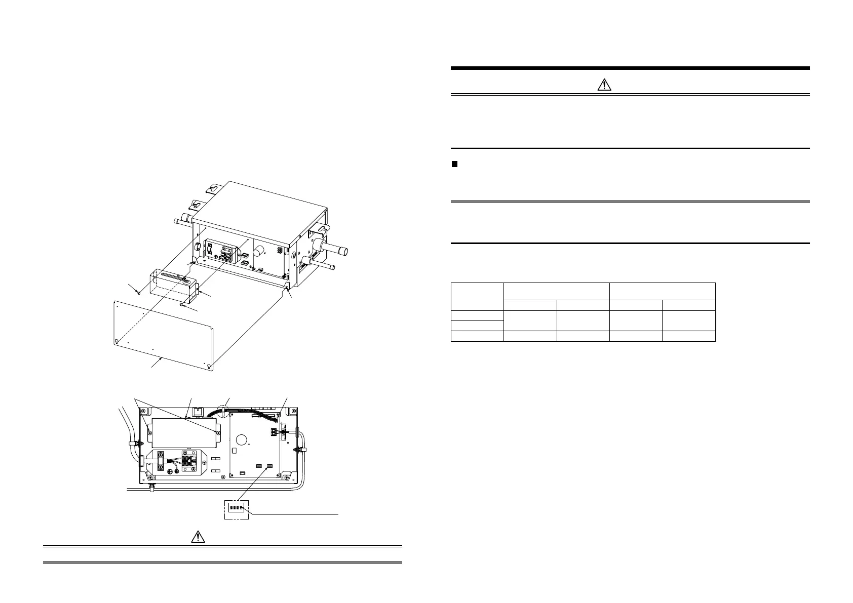
1. Loosen the cover mounting screws (2 positions) of the electrical control box, and then remove the cover.
2. Install the Battery kit with the two screws (accessory of Battery kit) in the orientation shown in the figure.
When installing the Battery kit, be careful not to let the Battery kit contact the P.C. board of Shut-off Valve unit
and do not pinch the wires with the Battery kit.
3. Connect the connector of the Battery kit to CN521 (RED) on the P.C. board of the Shut-off Valve unit, which is
located on the right side when viewed from the Battery kit.
4. Turn on the No.4 DIP switch of SW03 on the P.C. board where the connector is connected.
Screw
(Accessory)
Screw
Battery kit
Screw
(Accessory)
Electrical control box cover
Screw
SW03
1234
ON
Screw
(Accessory of Battery kit)
Battery kit Clamp to the wire clamp. Connect to CN521
Switch only the No.4 DIP switch
of SW03 to ON
CAUTION
Do not pull the wire too hard. The connector inside the Battery kit may come off.
4 REFRIGERANT PIPING
WARNING
If refrigerant gas has leaked during the installation work, ventilate the room immediately.
If the leaked refrigerant gas comes in contact with fi re, noxious gas may be generated.
After the installation work, confi rm that refrigerant gas does not leak.
If refrigerant gas leaks into the room and fl ows near a fi re source, such as a fan heater, cooking stove or heating
unit, noxious gas may be generated.
Permissible pipe length and permissible height difference
For piping dimensions, follow the Installation Manual attached to the outdoor unit.
REQUIREMENT
•
When the refrigerant pipe is long, set the support brackets to fi x the pipe at intervals of 2.5 to 3 m.
If the pipe is not fi xed, noise may be generated.
•
Never bend pipes sticking out of the unit.
The connecting pipework must be supported, failure to do so may result in broken Pipework within the unit.
■
Connection pipe size of Shut-off Valve unit (default)
(Unit : mm)
RBM–ȊȊȊ
Outdoor unit side
(Upstream)
Indoor unit side
(Downstream)
Gas pipe Liquid pipe Gas pipe Liquid pipe
SV1121HUPE
Ø15.9 Ø9.5 Ø15.9 Ø9.5
SV1801HUPE
SV6701HUPE Ø28.6 Ø15.9 Ø28.6 Ø15.9
8
EN-15 EN-16

 Loading...


