9
E6582171
2.2 Wiring
2.2.1 Connector
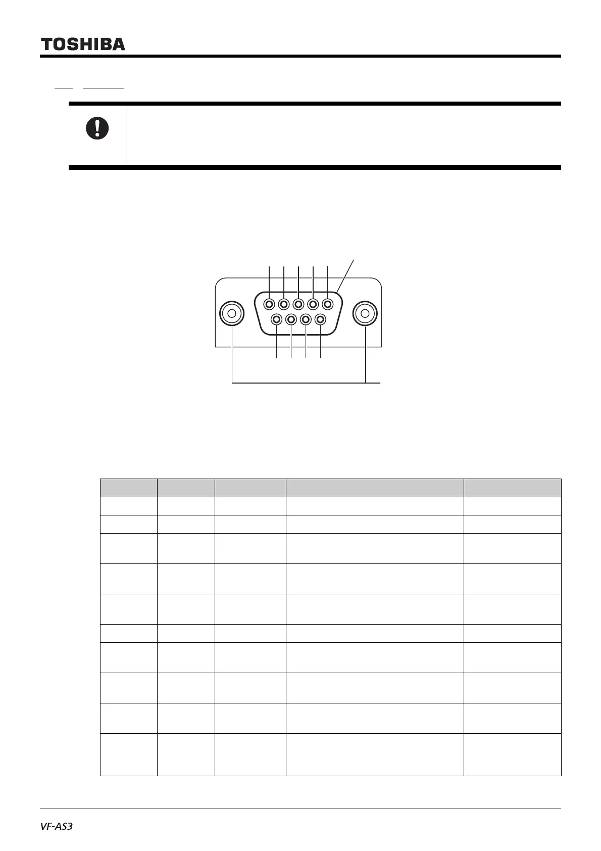
9pin D subminiature connector (DE-9) is prepared in this option. Pin numbers of connector are shown the figure in
below. Prepare the same type male connector separately for the cable end of interconnection cable.
Fig.2 - Resolver interface connector (D subminiature)
2.2.2 Pin assignment
Table 2-1. Pin assignment
Important
• This option is applicable with the feedback signal dedicated to resolver.
• Do not connect/disconnect the cable when the power on. it can damage the option.
No. Symbol Input/output Function / Electrical specifications Internal circuit
1- -(NC) -
2 - - (don’t use) -
3 S4 Input
Sinusoidal signal from resolver (–), pair
with S2 signal
Refer to (a)
4 S1 Input
Sinusoidal signal from resolver (+), pair
with S3 signal
Refer to (a)
5 R2 Output
Excitation voltage (+)
Carrier frequency 3 to 12kHz
Refer to (b)
6 - - (don’t use) -
7 S2 Input
Sinusoidal signal from resolver (+), pair
with S4 signal
Refer to (a)
8 S3 Input
Sinusoidal signal from resolver (–), pair
with S1 signal
Refer to (a)
9 R1 Output
Excitation voltage (–)
Carrier frequency 3 to 12kHz
Refer to (b)
Housing Shield -
Cable shield (metal housing of connector)
This part is connected to PE terminal
inside the inverter
-
1
SHIELD
6
789
2345
Female screw (4-40 UNC)
 Loading...


