11
E6582171
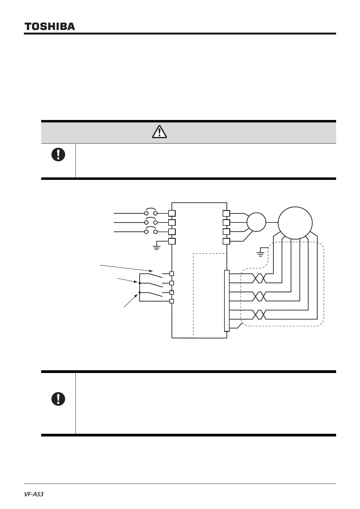
2.2.4 Wiring with resolver
When wiring, follow the instructions below.
- Use multi-layer shielded cable
- Use twisted pair for S1/S3, S2/S4 and R1/R2 each
- For R1/R2 pins, parameter set-up according to your resolver is also needed (See 3.1.1)
- Do not connect any wire to unused pins
- Recommended wire size is 0.25 mm
2
(AWG23) for signal line (S1,S2,S3,S4), 0.5 mm
2
(AWG20) for excitation
voltage (R1 and R2)
- The cable length is 100 m at maximum.
Fig.3 - Example of wiring for Resolver (Speed/Torque switching operation)
CAUTION
Mandatory
action
• Use Multi-layer shielded cable and connect the shield to housing of 15pin D subminiature connector.
Use of unshielded cable or improper shield grounding can result in malfunction or accident.
Important
• Separate the interconnection cable between your resolver and this option 20cm or more away from
power (Power supply and motor) cable to prevent from the signal disruption by noise immunity.
• Do not connect/disconnect the cable when the power on. it can damage the option.
• When prohibition on reverse rotation is set by the inverter parameter <F311: Reverse inhibited> = “1”
and when the motor is rotating to reverse direction due to an external force, the inverter starts with
reverse operation in accordance with the motor's rotation direction for a time and the motor will be able
to shift to the forward rotation and the smooth startup becomes possible.
Torque control with ON and reduce speed
and stop with OFF.
Set <F114 : Terminal S1 function 1> to “112”.
*1 Assign ST (standby) function to arbitrary terminals.
Forward rotation with ON and
reduce speed and stop with OFF
With OFF, free-run stop
VEC010Z
VF-AS3
Resolver
*
2
*2 Ground the shield at the
cable end of resolver side.
M
S1
S3
S2
S4
R1
R2
S1
S3
S2
S4
R1
R2
Housing
U
V
W
PE
R
S
T
PE
*
1
ST
F
S1
CC
 Loading...


