10 18-GE04D2-11
Installer’s Guide
COOLING OFF - DELAY OPTIONS
SWITCH SETTINGS SELECTION
NOMINAL
AIRFLOW
5 - OFF 6 - OFF NONE SAME
5 - ON 6 - OFF 1.5 MINUTES 100% *
5 - OFF 6 - ON 3 MINUTES 50%
5 - ON 6 - ON ENHANCED** 50 - 100%
* - This setting is equivalent to the BAY24X045 relay benefit
** - This ENHANCED MODE selection provides a ramping up
and ramping down of the blower speed to provide improved
comfort, quietness, and potential energy savings. The graph
shows the ramping process.
OFF OF
50%
80%
50%
Dehumidify
Fast Coil Cooling
and Heating
Efficiency
7.5
minutes
3
minutes
1
minute
FAN OPERATION (CFM)
COMPRESSOR OPERATION ON
OFF
as required
I. CONTROL WIRING
1. Connect wiring between indoor unit, outdoor unit
and thermostat. The use of color-coded low-voltage
wires is recommended.
2. A low voltage terminal board is provided for control
wiring, and is located on the left side of the cross
brace in the center of the unit.
3. Field wiring diagrams are provided which show the
low voltage wiring hookup for a single speed cool-
ing only system (with supplementary heaters) and a
heat pump system (with supplementary heaters).
Plug in type electrical connectors are provided for
use with supplementary heaters.
IMPORTANT:
When supplementary heaters are installed, inspect to
insure that all packaging material has been removed.
NOTE: Direct drive motors have bearings which are
permanently lubri-cated and under normal use lubri-
cation is not recommended.
J. AIRFLOW ADJUSTMENT
CAUTION
!
Disconnect power to the air handler before changing
dip switch positions.
Failure to follow this procedure may result in equip-
ment damage.
Blower speed changes are made on the ECM Fan Con-
trol mounted on the control box. The ECM Fan Control
controls the variable speed motor.
There is a bank of 8 dip switches (See Figure 17). The
dip switches work in pairs to match the airflow for the
outdoor unit size (tons), cooling airflow adjustment,
Fan off-delay options, and heating airflow adjustment.
The switches appear as shown in Figure 18.
If the airflow needs to be increased or decreased, see
the Airflow Label on the air handler or the Blower Per-
formance Table in the Service Facts.
Information on changing the speed of the blower motor
for your specific outdoor model size is in the Blower
Performance Table.
Be sure to set the airflow for the correct tonnage.
Refer to blower housing for correct setting.
Switches 1 - 4 Cooling Airflow
Switches 5 - 6 Fan Off Delay Options
Switches 7 - 8 Auxiliary Heat
If the optional humidistat is used, remove R-BK jumper
from the low voltage terminal board (not shown) and in-
stall the humidistat between R and BK. (Jumper R to O
for cooling-only/non-heat pump systems with a humidis-
tat.)
INDOOR BLOWER TIMING
The FAN-OFF period is set on the ECM Fan Control
board by dip switches #5 and #6. The blower off-delay
settings are as follows:
IMPORTANT:
Leave dip switch 5 & 6 in the "as-shipped" position
during system start-up and check out. Afterwards, ad-
just as desired.
DIP SWITCHES (AS SHIPPED)
COOLING
HEATING
AIRFLOW
FAN OFF
DELAY
AUXILIARY
HEAT SPEEDS
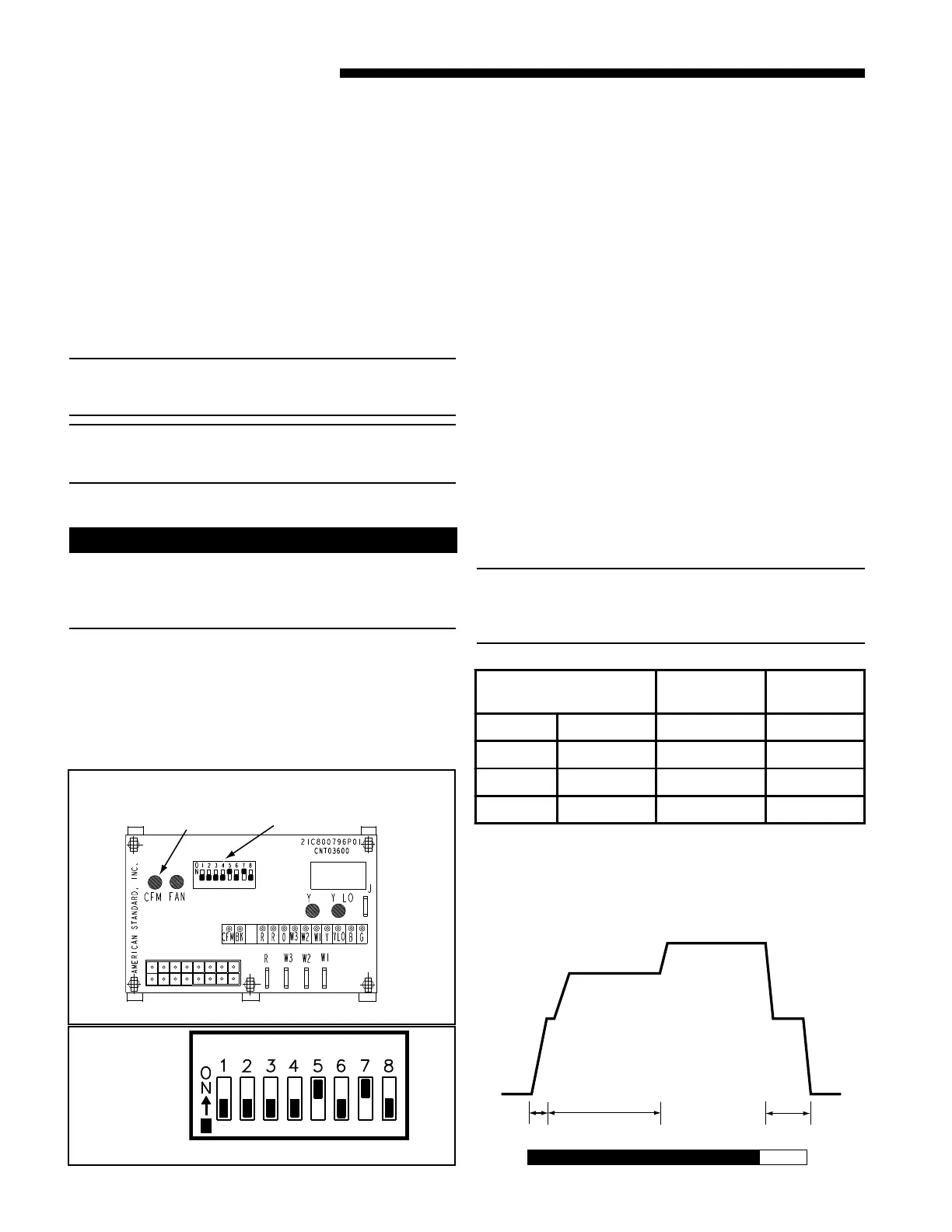
Figure 18
From Dwg. 800796a
SELECTION
LIGHT
DIP
SWITCHES
ECM FAN CONTROL
Figure 17
 Loading...

