6 18-GE04D2-11
Installer’s Guide
e. It is always recommended that an auxiliary drain
pan be installed under a horizontal air handler
(See Condensate Piping) to prevent possible dam-
age to ceilings.
f. Isolate the auxiliary drain pan from the unit or
from the structure.
g. Connect the auxiliary drain line to a separate
drain line (no trap is needed in this line) and ter-
minate according to national and local codes.
h. If a return duct is connected to the air handler, it
must be the same dimensions as the return
opening shown in the outline drawing on page
13.
i.
On units with sheetmetal returns: Return
plenum should be flanged. Sheetmetal screws
must be 1/2" in length or shorter.
j. No sheetmetal screws may be used to attach
return ductwork on the side of the unit.
k. Openings where field wiring enters the
cabinet must be completely sealed.
Location of power entry is shown on the outline
drawing. Use 2.5" clear stickers provided to seal
all unused electrical knockouts. See Figure 8.
l. After ductwork connections are made, seal air-
tight and per Local codes.
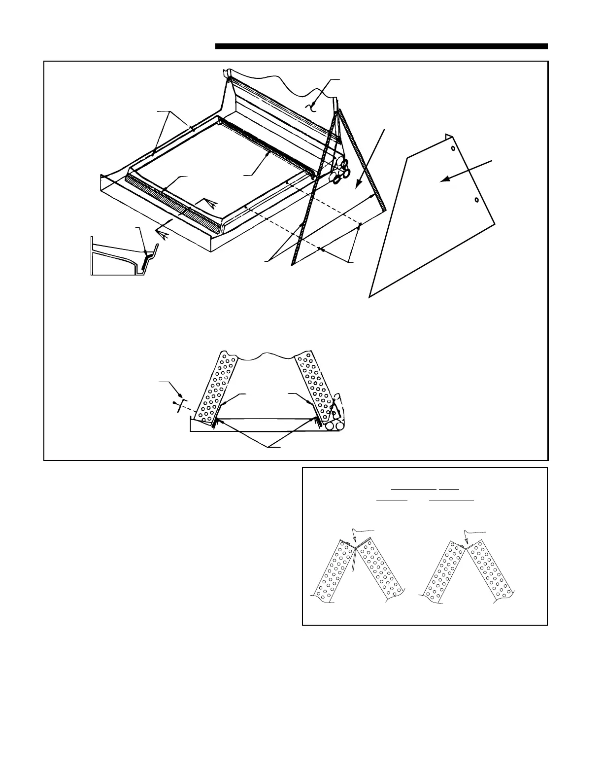
HORIZONTAL RIGHT
a. For maximum efficiency and Customer ease of
filter maintenance, it is recommended that a
Remove
and
Discard
Replac
with
Narrow
Baffle
For Maximum Efficiency on
Horizontal Left,
Upflow and Downflow
Figure 10
X
X
7/8" GASKET
SCREWS TO
REMOVE COIL
SCREWS TO
REMOVE COIL
DISCARD
DRIP TRAY
1/2" GASKET
INSIDE SURFACE
OF BAFFLE
/8" GASKET
SECT. X-X
TYP. BOTH SIDES)
WATER
BLOW-OFF
BAFFLES
ATTACH WITH
2 SCREWS
EACH SIDE
WATER
DIVERTER
BAFFLES
(5-ton only)
TRIANGULAR
BAFFLE
FRON
SHIEL
DOWNFLOW BAFFLE KIT
Figure 9
 Loading...

