2 18-AD43D1-1C-EN
Installer’s Guide
This coil is pressurized with 8-12 psig of dry air. Do
not stand directly in front of the coil connections when
removing sealing plugs. If no pressure is released, check
for leaks.
C. RECOMMENDATION
If a coil is part of the total system installation, use the Installer’s
Guide packaged with the furnaces, outdoor sections, and
thermostat for physically installing those components.
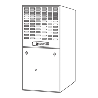
E. FURNACE IN DOWNFLOW POSITION
D. FURNACE IN UPFLOW POSITION
APPLICATION USES UPFLOW COIL MODEL ONLY
IMPORTANT:
If installing the coil in the horizontal position, you MUST
use the horizontal kit listed below for this coil model
number and follow the instructions in the installation
guide provided with the conversion kit.
Model Number Horizontal Kit No.
4PXCBU36BS3HAC
BAYCONV23B
4PXCBD36BS3HDC
4PXCDU60BS3HAC
BAYCONV30C
4PXCDD60BS3HDC
UPFLOW
FURNACE
CASED
COIL
SCREWS
(BO
1-1/2” MAXIMUM
FIELD SUPPLIED
FOR UPFLOW /
HORIZONTAL LEFT
INSTALLATIONS
Figure 2
Figure 4
Attach Downow
Bottom Gasket
Start
here
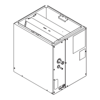
1. UPFLOW GAS FURNACE
a. Apply gasket material (duct seal eld supplied) to ALL
mating surfaces between the furnace and the coil case.
b. Set the coil case on top of the furnace. Connect the
ductwork to the coil case using eld supplied screws.
See Figure 2.
c. Secure the coil case to the furnace and seal for air
leaks as required.
This coil is pressurized with 8-12 psig of dry air. Do
not stand directly in front of the coil connections when
removing sealing plugs. If no pressure is released, check
for leaks.
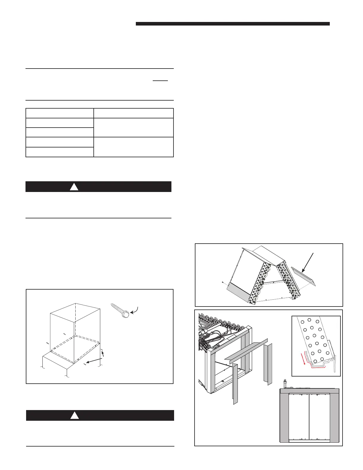
1. DOWNFLOW COIL CONVERSION
On 4PXCDD60BS and 4PXCDU60BS, installing the water
diverter baes is required for water management in downow
installations. Install the two outer water baes closest to the
drain pan using the provided 5/16" hex screws. See Figure 3.
2. DOWNFLOW GAS FURNACE
When a coil is used with a downow furnace, a subbase is not
required between the coil case and combustible ooring
a. Place the coil case on the furnace supply air plenum.
b. Secure the coil case to the plenum.
c. Set the furnace on top of the coil case, making sure that the
back side of the discharge opening is snug up against the
duct ange at the top rear of the coil case.
d. Secure the coil case to the furnace and seal for air
leaks as required.
3. DOWNFLOW GASKET INSTALLATION (OPTIONAL):
For unusually humid applications that expect prolonged operation
above 70% RH, it is recommended to use the BAYGSKT001A0
gasket kit to prevent water from forming on the bottom of the drain
pan and dripping into the supply ductwork.
a. Lay the coil on its back side.
b. Locate the 4" wide gasket material found in BAYGSKT001A0.
c. Attach the 4" gasket material to three sides of the bottom of
the drain pan as shown. Make sure to start by matching up
the edge of the gasket material to the inner edge of the drain
pan by the coil ns and working outwards.
d. The gasket material can be cut or ripped easily so that it can
be tailored to t. The gasket material must cover the three
sides along the entire length of the coil as shown in Figure 4.
WATER DIVERTER (X2)
Figure 3
 Loading...