18-AD43D1-1C-EN 3
Installer’s Guide
F. MAXIMUM AIRFLOW SETTING (CFM)
NOTE:
Water blow-o could occur in certain installation
positions if the airow setting exceeds the maximum
values listed.
Maximum airow settings (CFM)
Coil Upow Downow
Horizontal
Left
Horizontal
Right
4PXCBU36BS3HAC 1350 1100 1200 1350
4PXCBD36BS3HDC N/A 1100 N/A 1350
4PXCDU60BS3HAC 2250 1850 2000 2250
4PXCDD60BS3HDC N/A 1850 N/A 2250
G. INSTALLING / BRAZING REFRIGERANT LINES
Do NOT open refrigerant valve at the outdoor unit until
the refrigerant lines and coil have been brazed, evacuated,
and leak checked. This would cause contamination of
the refrigerant or possible discharge of refrigerant to the
atmosphere.
1. The following steps are to be considered when installing
the refrigerant lines:
a. Determine the most practical way to run the lines.
b. Consider types of bends to be made and space
limitations.
c. Route the tubing making all required bends and
properly secure the tubing before making nal
connections.
NOTE:
Refrigerant lines must be isolated from the structure and
the holes must be sealed weather tight after installation.
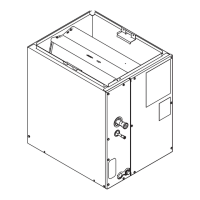
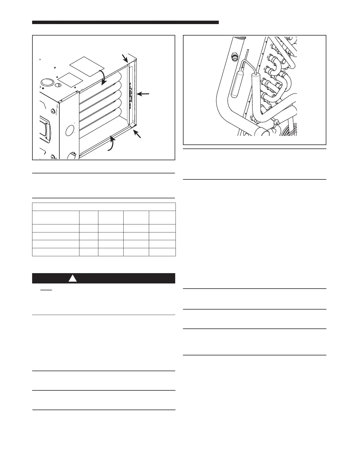
Figure 5
Note: For S-series furnaces, bend outlet anges in-
ward or outward to suit installation. Coil and furnace
will nest together.
NOTE:
TXV bulb MUST be protected (wrapped with wet rag) or
removed, while brazing the tubing. Overheating of the
sensing bulb will aect the functional characteristics and
performance of the comfort coil.
1. Remove both rubber plugs from the indoor coil.
2. Field supplied tubing should be cut square, round and free
of burrs at the connecting end. Clean the tubing to prevent
contaminants from entering the system.
3. Run the refrigerant tubing into the stub tube sockets of the
indoor unit coil.
PAINTED AREAS OF THE UNIT MUST BE SHIELDED DURING
BRAZING.
4. Flow a small amount of nitrogen through the tubing while
brazing.
5. Use good brazing technique to make leakproof joints.
6. Minimize the use of sharp 90 degree bends.
7. Insulate the suction line and its ttings.
8. Do NOT allow un-insulated lines to come into contact with
each other.
NOTE:
When replacing the TXV bulb, reinstall the bulb in the
proper orientation using the spring clip provided.
9. Rewrap the TXV bulb, spring clip, and suction line with
insulation after spring clip is reinstalled.
NOTE:
The TXV setting may run high superheat when measured
at the outdoor unit (15-25 °F) for upow and horizontal left
installations.
10. For optimal performance, the TXV bulb may be relocated
outside the coil cabinet after the eld line brazing is
complete.
a. Remove the bulb insulation and bulb clip.
b. Lace the TXV bulb through the large coil panel
grommet.
c. Assemble the TXV bulb to the eld provided suction
line outside the unit. Ensure the bulb is mounted on
a straight, smooth section of 7/8" O.D. copper line.
The bulb should be clear of any eld braze joints and
located away from any bends in the pipe.
Figure 6
IMPORTANT:
Do not unseal refrigerant tubing until ready to t refrigerant
lines.
There is only a holding charge of dry air in the indoor coil,
therefore no loss of operating refrigerant charge occurs when
the sealing plugs are removed.
 Loading...