4 18-AC79D1-10E-EN
2.4 Cold Climate Considerations
NOTE: It is recommended that these precautions be taken for units being installed in areas where snow accumula-
tion and prolonged below freezing temperatures occur.
• Units should be elevated 3-12 inches above the pad or roof top, depending on local weather. This additional
height will allow drainage of snow and ice melted during defrost cycle prior to its refreezing. Ensure that drain
holes in unit base pan are not obstructed preventing draining of defrost water.
• If possible, avoid locations that are likely to accumulate snow drifts. If not possible, a snow drift barrier should be
installed around the unit to prevent a build-up of snow on the sides of the unit.
2.5 Coastal Considerations
If installed within one mile of salt water, including seacoasts and inland waterways, models without factory sup-
plied Seacoast Salt Shields require the addition of BAYSEAC001 (Seacoast Kit) at installation time.
STEP 2 - To remove the unit from the pallet, remove tabs by cutting with a sharp tool.
Section 3. Unit Preparation
3.1 Prepare The Unit For Installation
STEP 1 - Check for damage and report promptly to the carrier any damage found to the unit.
Section 4. Setting the Unit
4.1 Pad Installation
When installing the unit on a support pad, such as a concrete slab, consider the following:
• The pad should be at least 1” larger than the unit on all sides.
• The pad must be separate from any structure.
• The pad must be level.
• The pad should be high enough above grade to allow for drainage.
• The pad location must comply with National, State, and Local codes.
For other applications refer to application guide.
Section 5. Refrigerant Line Considerations
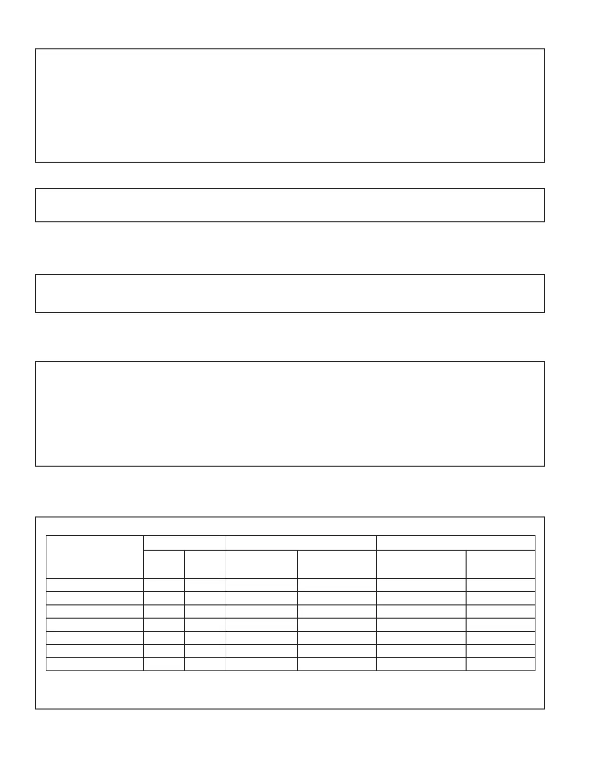
5.1 Refrigerant Line and Service Valve Connection Sizes
Table 5.1
RATED
LINE SIZES
Line Sizes Service Valve Connection Sizes Max Line & Lift Lengths
Vapor
Line
Liquid
Line
Vapor Line
Connection
Liquid Line
Connection
TOTAL Max
Line Length (ft.)
Max Lift (ft.)
4TTR3018N
3/4 3/8 3/4 3/8 150 50
4TTR3024N
3/4 3/8 3/4 3/8 150 50
4TTR3030N
3/4 3/8 3/4 3/8 150 50
4TTR3036N
3/4 3/8 3/4 3/8 150 50
4TTR3042N
7/8 3/8 7/8 3/8 150 50
4TTR3048N
7/8 3/8 7/8 3/8 150 50
4TTR3060N
7/8 3/8 7/8 3/8 150 50
Note: For other line lengths, Refer to Refrigerant Piping Application Guide, SS-APG006-EN or Refrigerant Piping
Software Program, 32-3312-xx (latest revision).
 Loading...