18-AC79D1-10E-EN 9
Section 11. Electrical - Low Voltage
11.1 Low Voltage Maximum Wire Length
Table 11.1 defines the maximum total length of
low voltage wiring from the outdoor unit, to the
indoor unit, and to the thermostat.
Table 11.1
24 VOLTS
WIRE SIZE MAX. WIRE LENGTH
18 AWG 150 Ft.
16 AWG 225 Ft.
14 AWG 300 Ft.
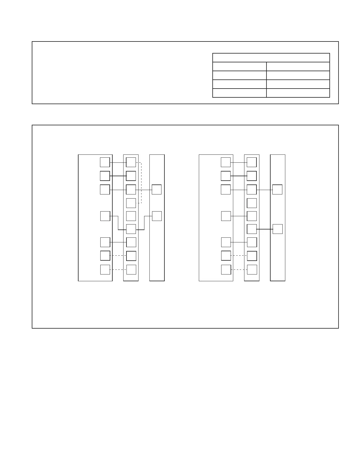
11.2 Low Voltage Hook-up Diagrams
With TEM 3, 4, 6, 8With TAM 4, 7, 9
• Units with pigtails require wirenuts for connections. Cap all unused wires.
•
In AC systems for multiple stages of electric heat, jumper W1 and W2 together if comfort control has only one stage of heat.
TEM3/4 - Bypass air handler and connect Y from comfort control directly to OD unit
y
** TEM6 only - When using a BK enabled comfort control, cut BK jumper and bypass Y1 and Y2 at the air handle
r. Connect BK from comfort
control to BK of the air handle
r
TAM4 only - Wire as shown, no BK is available
TAM7 only - When using a BK enabled comfort control, cut BK jumper on the AFC and connect BK from comfort control to BK of the air handle
Thermostat Air Handler
Outdoor
Unit
R
G
B
W1
W2
B
Y
R
G
B/C
Y
W1
W2
Blue
24 VAC HOT
FAN
24 VAC
Common
SOV
COOL/HEAT
1st STAGE
HEATING
2nd STAGE
EMERGENCY
HEAT
Pink
White
O
Y1
Y2
*
BK
WH/BLK
BK
WH/BLK
Thermostat Air Handler
Outdoor
Unit
R
G
B
W1
W2
B
R
G
B/C
Y
l
W1
W2
Blue
24 VAC HOT
FAN
24 VAC
Common
SOV
COOL/HEAT
1st STAGE
HEATING
2nd STAGE
EMERGENCY
HEAT
Pink
White
O
Y
l
Y
O
Y
O
BK
WH/BLK
BK
WH/BLK
**
 Loading...